
Polo Mk5
| Removing and installing timing chain and chain drive for oil pump |
| Special tools and workshop equipment required |
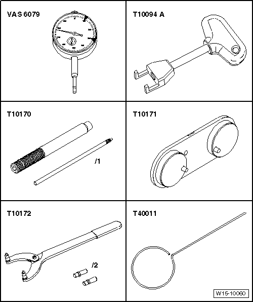
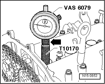
| t | Dial gauge -VAS 6079- |
| t | Puller -T10094 A- |
| t | Dial gauge adapter -T10170- |
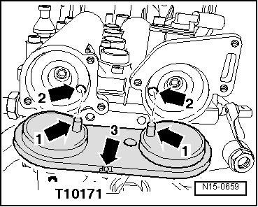
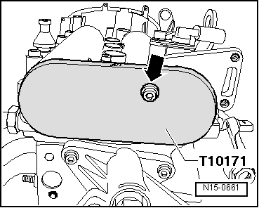
| t | Camshaft clamp -T10171- |
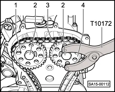
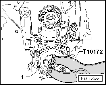
| t | Counterhold tool -T10172- |
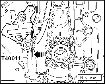
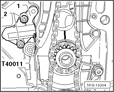
| t | Locking pin -T40011- |
|
|
|
|
|
|
|
|
|
|
 Note
Note
|
|
|
|
|
|
|
|
|
|
|
|
|
|
|
|
|
|
|
|
 Caution
|
|
Note
|
|
|
|
Note
|
|
Note
|
|
|
|
|
|
Note
|
|
|
|
Note
|
|
|
|