
Polo Mk5
|
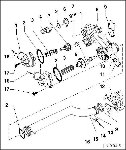
| 1 - | Connection |
| 2 - | O-ring |
| q | Renew. |
| 3 - | Spring |
| 4 - | Coolant temperature sender -G62- |
| q | Before removing, release pressure in cooling system if necessary. |
| 5 - | Plunger |
| q | Do not interchange when installing |
| 6 - | Retaining clip |
| q | Check for secure seating. |
| 7 - | 10 Nm |
| 8 - | Thermostat housing |
| 9 - | Seal |
| q | Renew. |
| 10 - | To heat exchanger |
| q | Coolant hose schematic diagram → Chapter. |
| 11 - | From heat exchanger |
| q | Coolant hose schematic diagram → Chapter. |
| 12 - | Coolant pump housing on cylinder block |
| 13 - | Connection |
| 14 - | To coolant expansion tank |
| q | Coolant hose schematic diagram → Chapter. |
| 15 - | Coolant pipe |
| q | Coolant hose schematic diagram → Chapter. |
| 16 - | Thermostat |
| Control range |
| q | long thermal element 87…102 °C |
| q | short thermal element 103…120 °C |
| q | Do not interchange when installing |
| 17 - | 5 Nm |
| 18 - | From top of radiator |
| q | Coolant hose schematic diagram → Chapter. |
| 19 - | To bottom of radiator |
| q | Coolant hose schematic diagram → Chapter. |
|
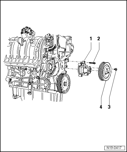
| 1 - | Coolant pump |
| q | Removing and installing → Chapter. |
| q | Check for ease of movement. |
| q | With integrated seal. |
| q | If damaged or leaking, renew complete. |
| 2 - | Bolt |
| q | 10 Nm |
| q | Qty. 4. |
| 3 - | Bolt |
| q | 20 Nm |
| q | Qty. 3. |
| 4 - | Belt pulley |
| q | Use water pump wrench -V.A.G 1590- or counterhold -T10172- to loosen and tighten |
| q | Locate counterhold -T10172- → Anchor |
| q | -V.A.G 1590- Modify → Chapter |
| q | When installing note fixing arrangement. |
| q | Removing and installing poly V-belt → Chapter. |