
Up!
|
 Note
Note
|
|
Note| Forms other than the covers -4 and 6- shown here may also be installed. |

| l | Lock cylinder cover cap is removed → Chapter |
| – | Lift covers -4 and 6-. |
| – | Remove bolt -5-. |
| – | Screw out bolt -7- to stop. |
| – | Press in bolt -7-. Only then is the lock cylinder released. |
| – | Pull door handle -2- off door -8-. |
| – | Pull lock cylinder housing -1- out of door handle bracket -3- keeping lock cylinder housing at right angles -arrow b- to the door. |
|
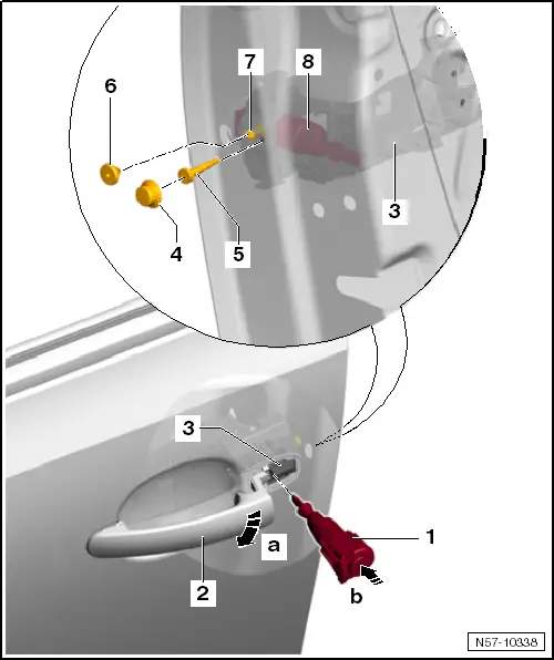
| – | Pull door handle -2- off door -8--arrow a-. |
| – | Push lock cylinder housing -1- into door handle bracket -3- at a right angle -arrow b-. |
| – | Screw bolts -5 and 7- into door handle bracket. |
| – | Specified torque for bolts -5 and 7-: 3.5 Nm. |
Note| During installation, lock cylinder housing must be pressed against outer door panel. |
| Further installation is performed in the reverse order of removal. |
| l | It is essential that a functional check is then performed with the door open. |