
Up!
| ABS/ESP |
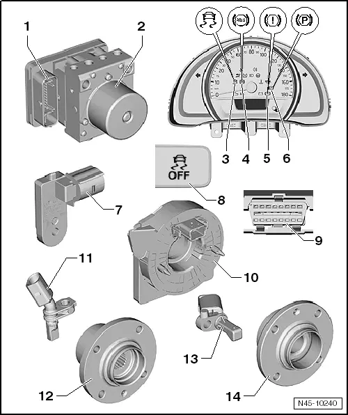
| 1 - | ABS control unit -J104- |
| q | Location: on hydraulic unit, on left in engine compartment, under battery tray. |
| q | Do not separate connector before successfully completing self-diagnosis. Switch ignition off before separating connector. |
| The following components are integrated into the control unit: |
| t | Lateral acceleration sender -G200- |
| t | Yaw rate sender -G202- |
| t | Longitudinal acceleration sender -G251- (depending on equipment fitted) |
| q | Removing and installing → Chapter. |
| 2 - | ABS hydraulic unit -N55- |
| The hydraulic unit consists of the components: |
| q | ABS return flow pump -V39- |
| q | Brake pressure sender -G201- |
| q | Valve block (contains inlet and outlet valves). |
| q | ABS return flow pump -V39- and valve block should not be separated from each other |
| q | Removing and installing → Chapter. |
| 3 - | ESP and TCS warning lamp -K155- |
| q | Location: in dash panel insert. |
| 4 - | ABS warning lamp -K47- |
| q | Location: in dash panel insert. |
| 5 - | Brake system warning lamp -K118- |
| q | Location: in dash panel insert. |
| 6 - | Parking brake warning lamp -K139- |
| q | Location: in dash panel insert. |
| 7 - | Brake light switch -F- |
| q | Including brake pedal switch -F47-. |
| q | Removing and installing → Chapter. |
| 8 - | TCS and ESP button -E256- |
| q | Location: in centre console. |
| 9 - | Diagnostic connection |
| q | Location: Driver footwell cover. |
| 10 - | Steering angle sender -G85- |
| q | Location: on steering column between steering wheel and steering column switch. |
| q | Observe installation instructions. |
| → Chapter |
| 11 - | Front right/left speed sensor -G45-/-G47- |
| q | Removing and installing → Chapter. |
| 12 - | Wheel hub with wheel bearing |
| q | ABS sensor ring is installed in wheel bearing. |
| 13 - | Rear right/left speed sensor -G44-/-G46- |
| q | Removing and installing (drum brakes) → Chapter |
| 14 - | Wheel hub with wheel bearing |
| q | ABS sensor ring is installed in wheel bearing. |