
240 L4-2.3L SOHC VIN 88 B230F (1986)
Fan Switch Plug
3. Join blower motor connectors (arrow).
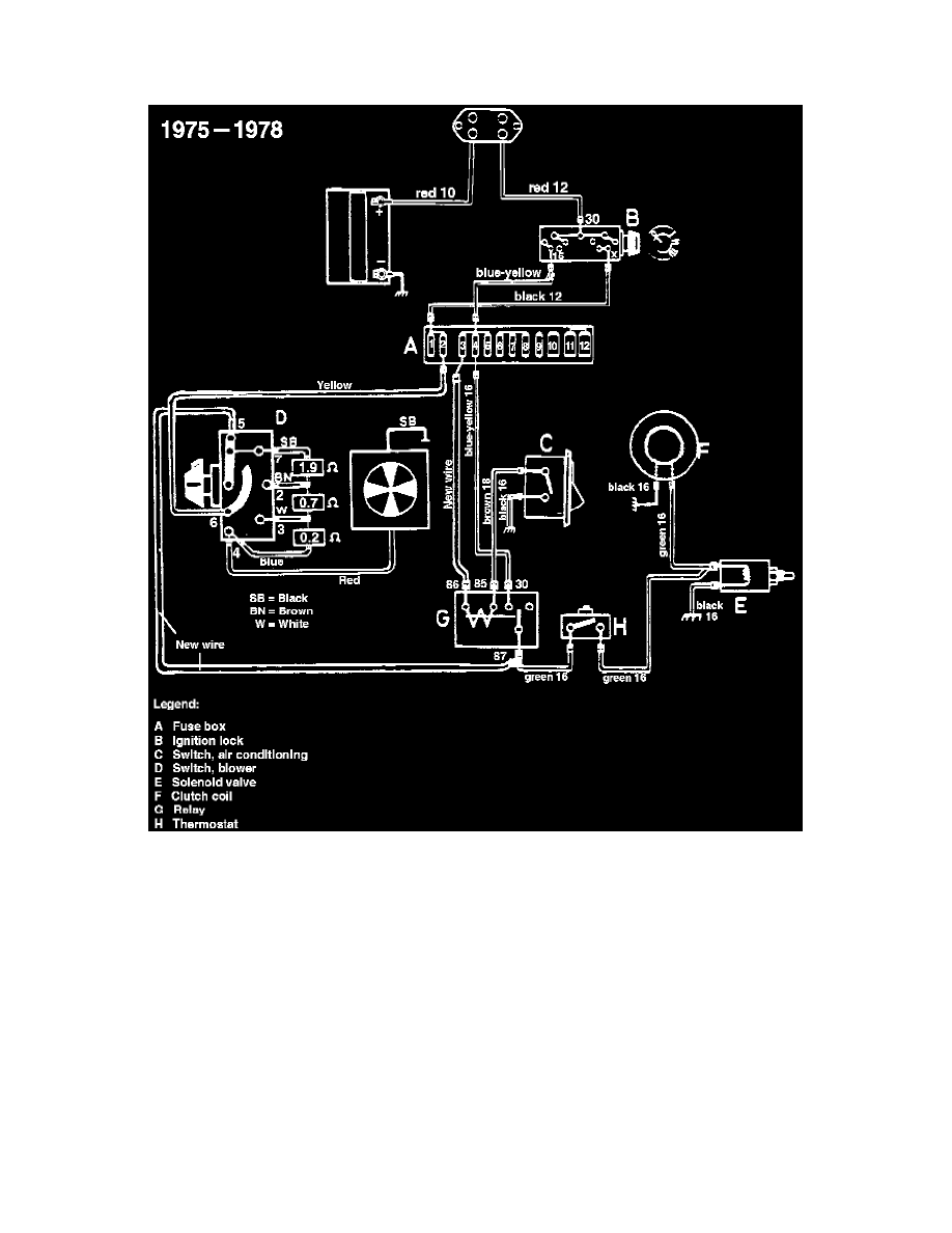
Modified Blower Motor Wiring Diagram
4. Install the yellow wire which was previously located in pin #3 of the old fan switch plug into pin #6 of the new switch plug. Refer to schematic.
5. The opposite end of the yellow wire is connected to fuse #2. Refer to schematic.
6. Use a new wire and connect it from pin #5 on the fan switch plug to terminal #87 on the AC-relay. Refer to schematic.
7. Use a new wire and connect it from fuse #3 to terminal #86 on the AC-relay. Refer to schematic.