
780 V6-2849cc 2.8L SOHC B280F (1987)
Overdrive Unit, A/T: Description and Operation
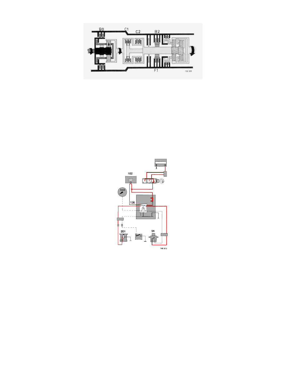
4th Gear (3rd + overdrive)
4th Gear (3rd + overdrive)
Fourth gear (overdrive), which is engaged automatically from 3rd, lowers the reduction ratio from 1:1 to 0.69:1 in the AW70/AW71.
Brake B0 is applied on engagement, locking the sun wheel in the overdrive unit.
The overdrive unit ring gear then rotates at a higher speed than the engine. This speed is transmitted to clutch C1 in the gearbox, from whence
the power is transmitted further to the output shaft as in 3rd gear (see above).
Overdrive may also be disengaged completely, permitting the gearbox to be used in 1st, 2nd and 3rd gears only. Disengagement is performed
by means of a switch (Overdrive Switch ) on the gear selector lever.
Wiring Diagram - 4th Gear Engaged
4th gear engaged
When 4th gear is engaged (the normal situation), solenoid valve 201 is energized by stepping relay 136.
The solenoid valve controls the fluid flow in the control system so that 4th gear is engaged and indicating lamp 102 is extinguished.