
940 L4-2.3L SOHC VIN 88 B230F (1992)
The blue-green cable which joins the blue-green cable should give a reading of 1-50 between the cable and ground.
If both values are correct, continue to A4. If the readings are not within the range, continue to A3.
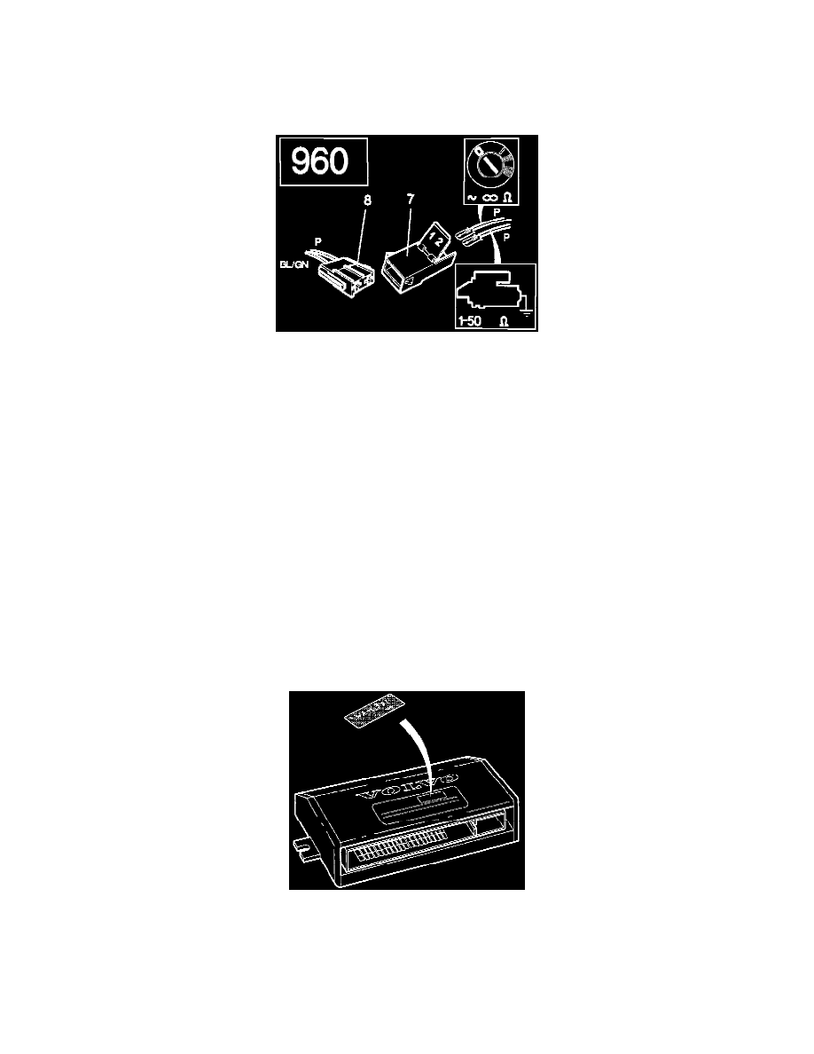
960 1993-94
Use an ohmmeter between one of the two pink cables and ground.
The pink cable which joins the pink cable in the connector should give a reading of (infinite resistance) between the cable and ground.
The pink cable which joins the blue-green cable should give a reading of 1-50 between the cable and ground.
If both values are correct, continue to A4. If the readings are not within the range, continue to A3.
A3
ADJUSTING THE STARTER INHIBITOR SWITCH
If the readings obtained are outside the range and the reason for this is incorrectly connected cables in the connector, the cables must be reversed and the
alarm control module replaced with a new one, after cable adjustment.
A4
CHECKING THE WEEK OF MANUFACTURE OF THE ALARM CONTROL MODULE.
Locate the alarm control module.
If the module in the vehicle is manufactured earlier than W20 1993, replace with a new one. replacement part P/N 9124542-3.
The week of manufacture is given on the label on the control module. The designation W320-X means Week 20 in 1993.
A5
CHECKING THE WEEK OF MANUFACTURE OF REMOTE CONTROL TRANSMITTERS.