
940 L4-2.3L SOHC VIN 88 B230F (1992)
Hydraulic Control Assembly - Antilock Brakes: Service and Repair
HYDRAULIC MODULATOR, REPLACEMENT (LATER VERSION)
Location: Engine compartment
Note that pipe connections 'h' and 'l' are now size M12 compared with M10 previously.
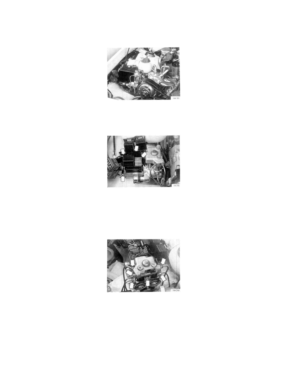
Illustration shows location in car with B 280 engine.
With certain engine options, hydraulic modulator is mounted on left-hand wheel housing.
AT1. Ensure that ignition is switched off
AT2. Remove/disconnect:
^
battery ground lead
^
cover over hydraulic modulator
^
both relays and connector
^
ground lead from modulator
AT3. Place cloth waste under modulator to collect brake fluid spillage
Carefully clean area around modulator connections.
Note: Mark position of each brake pipe with particular care.
Mark pipes with the same letters as on modulator (V, H, l, r, h).
Also see schematic showing all brake pipe connections on following page.
AT4. Remove hydraulic modulator
Disconnect brake pipes from unit. Remove support bracket bolt (see illustration) and move bracket aside.
Installation