
940 L4-2.3L SOHC VIN 88 B230F (1992)
Hydraulic Control Assembly - Antilock Brakes: Description and Operation
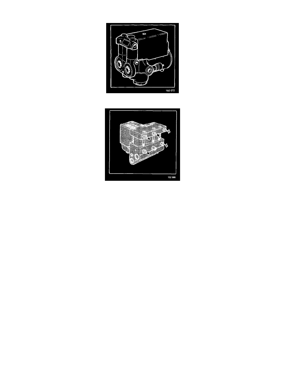
Hydraulic Modulator (M10)
Hydraulic Modulator (M12)
The hydraulic modulator receives and processes the control module signals so as to maintain the correct pressure in the wheel cylinders. In the event
of wheel lock, the pressure in the brake cylinder of the locked wheel is reduced and the integral electrical control pump returns brake fluid from the
wheel cylinder to the master cylinder.
A later version of the hydraulic modulator is provided with new pipe connections at two points. The outlets in question are marked 'h' (rear circuit
outlet) and 'i' (left front outlet). Since the size of the new outlets is M12 compared with M1O previously, the brake pipes must also be replaced when
replacing an earlier modulator with the new type.
A completely new type of modulator was introduced on models from 1992 on (see illustration).
The piping and connector arrangement is completely different on the new version which, as a result, cannot be installed in earlier models.