
940 L4-2.3L SOHC VIN 88 B230F (1992)
Diagnostic Socket Description
FUNCTION
This diagnostic socket is used for communication with the diagnostic functions in the fuel injection and ignition ECU.
The diagnostic socket consists of a button, an LED and a selector cable. For fault tracing on the fuel injection system, the selector cable is placed
in output #2. By pressing the button once, twice or three times (depending on control function required), the fuel injection ECU is accessed.
Control function #1:
This control function will access the fuel injection ECU memory and extract any recorded faults.
Faults stored in the ECU are read via "fault codes" consisting of flashes at the LED.
Control function #2:
This is a function to test selected input components in the fuel injection system. These are the throttle position, RPM, AC compressor and gear
selector (A/T only) signal.
Control function #3:
This is used with the engine stopped. Selected output components are automatically tested and activated to check correct operation.
Ignition
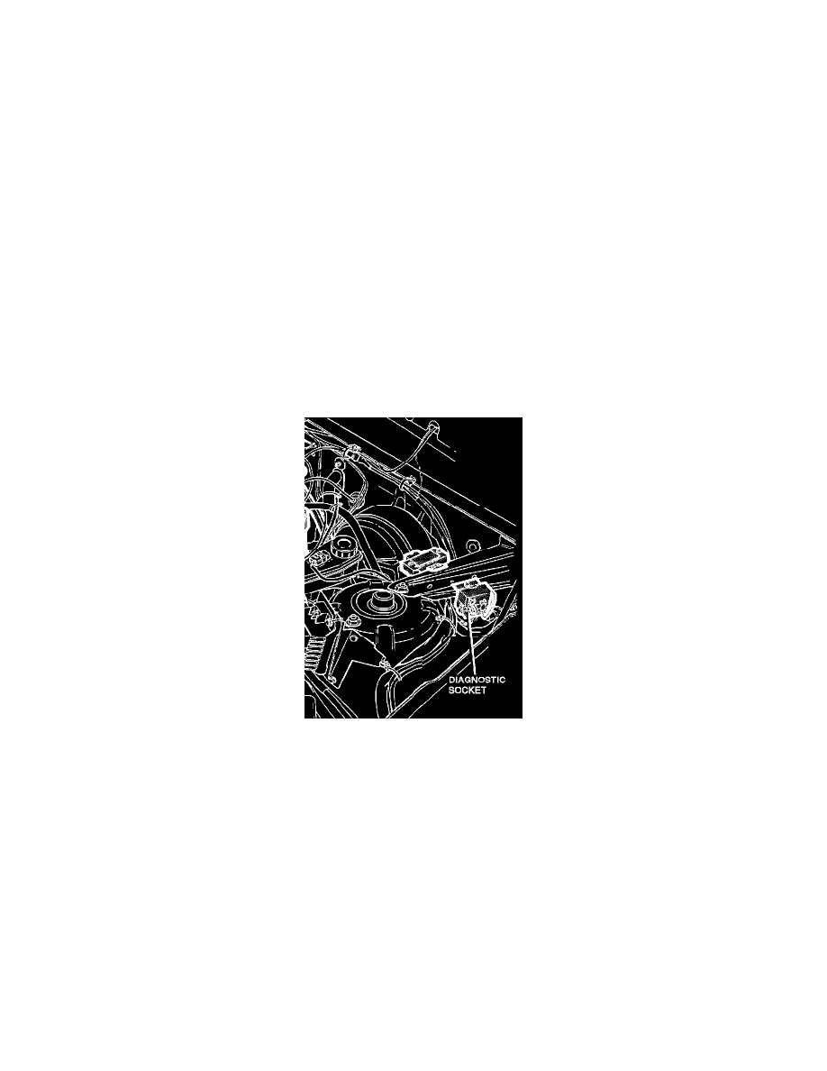
Diagnostic Socket Location
PURPOSE AND LOCATION
The ignition ECU has a self diagnostic and function test system. These are combined with the diagnostic and function test system of the fuel
injection ECU.
The diagnostic system of the ignition ECU is capable of detecting 5 faults and storing three different codes in its memory. The ECU continuously
monitors the following functions during driving:
^ Control unit internal functions
^ Knock sensor signal
^ Coolant temperature sensor
^ Engine speed and position signal
^ Engine load signal
To check the fault code memory or a component, you must access the diagnostic socket located in the engine compartment behind the left
suspension tower.