
940 L4-2.3L SOHC VIN 88 B230F (1992)
Checking Pin 1
10.
Check diagnostic socket by turning ignition ON.
11.
Place selector cable into pin #6.
12.
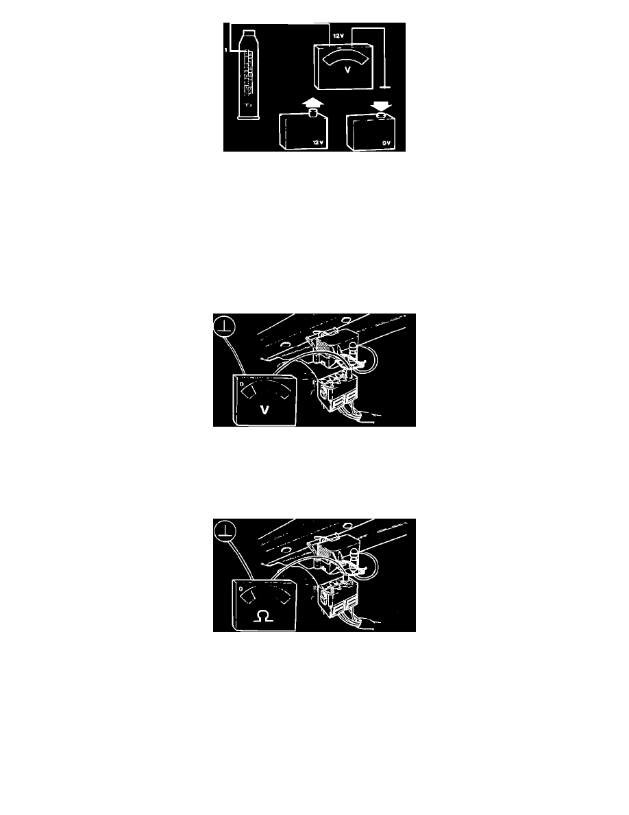
Connect a voltmeter between ground and pin 1 (yellow-red) at ECU connector.
a. Reading: 12 volts.
b. Reading: 0 volt when button is depressed.
13.
If O.K., diagnostic socket is working correctly. See step 24.
14.
If the diagnostic socket fails the test, see next step.
Checking Socket Red-Black Wire
15.
Disconnect diagnostic socket connector.
16.
Connect voltmeter between blue wire and ground.
Reading: 12 volts
Checking Socket Brown-Black Wire
17.
Connect an ohmmeter between black wire and ground.
Reading: 0 ohm