
940 L4-2.3L SOHC VIN 88 B230F (1992)
Checking Battery Supply
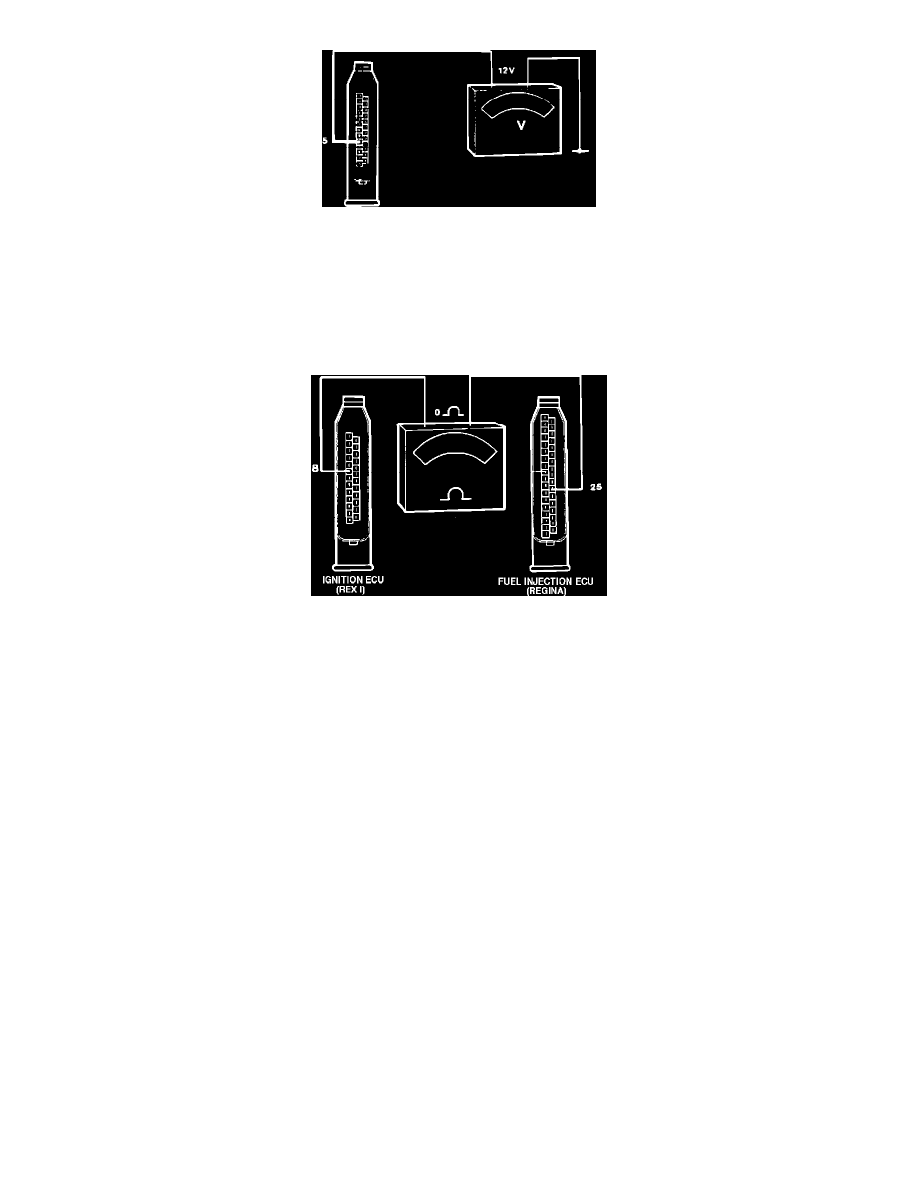
8.
Check main power supply by connecting a voltmeter between pin 5 (brown) in ECU connector and ground.
Reading: approx. 12 volts
9.
If no voltage registers, check wire between ECU and fuse-box located behind the center console ash tray. Check fuse #1 and wiring to battery
(incl. battery terminals). Repair as necessary.
Checking Engine Load Signal Wire
10.
Remove panel under right-hand side kick panel. Make sure ignition is in the off position. Remove glove box and undo fuel injection ECU
connector.
11.
Connect an ohmmeter and measure the resistance between pin 8 of ignition ECU and pin 25 of fuel injection ECU connectors.
Reading: 0 ohm
12.
If ohmmeter gives different reading, check wiring and connectors. If they are in good condition, either ignition or fuel injection ECU is faulty or
check ECUs as described by COMPONENT TESTING under TESTING PROCEDURES. Repair as needed.
13.
After testing, disconnect all test equipment, reconnect all connectors (including the ECU connectors) and remount all panels.
14.
Erase fault codes and test drive vehicle. Recheck for fault codes.