
940 L4-2.3L SOHC VIN 88 B230F (1992)
Throttle Cable/Linkage: Adjustments
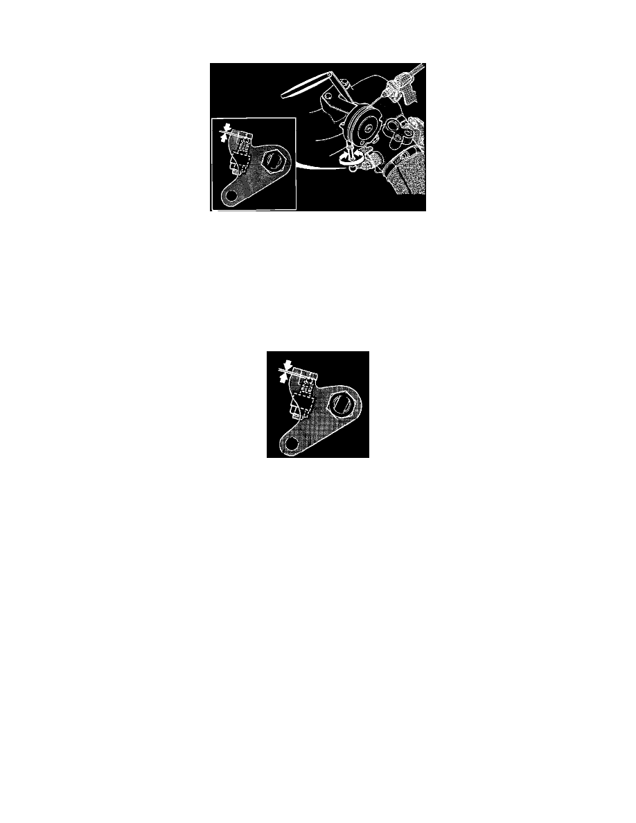
ADJUSTING THROTTLE MECHANISM
Fig. 360 CONNECT AND ADJUST LINK ROD
Adjusting the Link Rod
^
Install the link rod.
^
Lock the ball joints on the link rod with the snap fasteners.
^
Put a 2.5 mm feeler gauge at the throttle pulley stop.
^
Turn the middle of the link rod until the throttle lever is not in contact with the adjustment screw and the TP switch clicks.
^
Then turn the link rod the other way until the return click is heard from the TP switch.
^
Tighten the link rod lock nuts, first by hand and then with a spanner to 0.6 ± 0.15 Nm (0.44 ± 0.1 ft lb). Hold the link rod so it does not turn with
the lock nut.
Checking Throttle Lever Play
^
Put a 2.5 mm feeler gauge at the throttle pulley stop.
^
Check:
-
That a 0.45 mm feeler gauge will not fit between the throttle lever and the adjustment screw.
-
That a 0.10 mm feeler gauge will fit between the throttle lever and the adjustment screw.
^
If play is not within these limits remove the lock nuts on the link rod and start again.
^
When you have finished adjusting throttle lever, remove the feeler gauge at the throttle pulley stop.