
940 L4-2.3L SOHC VIN 88 B230F (1992)
Engine Control Module: Connector Views
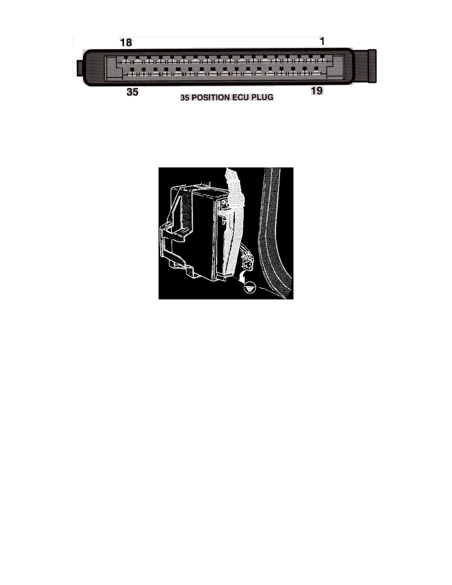
35 Position ECU Plug
PIN LAYOUT
SYSTEM
LH-Jetronic
Checking ECU Ground Connections
LOCATION
Kick panel passenger side
TERMINAL ID
1 - From EZK ECU Trigger signal (Pin 17)
2 - Closed throttle
3 - Full load Throttle (non-turbo only)
4 - Battery (+) feed
5 - Ground
6 - Air Mass Meter Supply
7 - Air Mass Meter Load
8 - Air Mass Meter Burn-off
9 - Main Relay Supply
10 - NO CONNECTION
11 - NO CONNECTION
12 - Diagnostic Connector
13 - Coolant Temperature Sensor
14 - A/C Compressor cut-off relay
15 - A/C Control Switch
16 - NO CONNECTION
17 - Ground
18 - Injector Driver (4)
19 - Ground
20 - Fuel Pump Relay Control
21 - Main Relay Control
22 - Instrument Cluster
23 - NO CONNECTION
24 - O2 Sensor Signal
25 - Output to EZK ECU