
940 L4-2.3L SOHC VIN 88 B230F (1992)
Hydraulic Control System: Description and Operation
HYDRAULIC CONTROL SYSTEM
The function of the hydraulic control system is to perform the actual gear-shifting operations and to determine which gear is to be selected at any
time.
The system consists of a number of interacting hydraulic valves actuated by oil supplied under pressure by a pump driven by the torque converter.
The system controls the planetary drive assembly in the gearbox, ensuring that it operates in a gear appropriate to the throttle position, vehicle
speed, terrain and gear position (as selected manually).
The hydraulic circuits are supplied at a constant line pressure which is converted and controlled so as to ensure that the clutches and brakes are
operated in the correct order. This is achieved by means of a number of hydraulic valves assembled in three valve bodies and forming a compact
hydraulic unit.
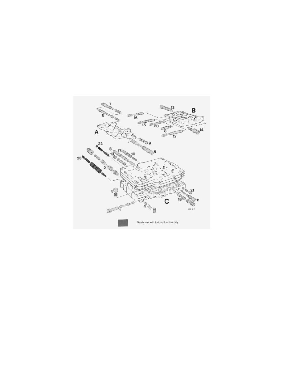
The valve locations are illustrated below.
Control System Assembly
A Upper front valve body
B Upper rear valve body
C Lower valve body
1. Gear selector valve
2. Primary regulator valve
3. By-pass valve
4. Relief valve
5. Secondary regulator valve
6. Throttle valve
7. Kickdown valve
8. Governor modulator valve (aluminium plug) (earlier AW70/71s are fined with steel valve and spring)
9. Cutback valve
10. Shift valve 1-2
11. Downshift valve, manual 2-1
12. Modulator valve, manual 2-1
13. Shift valve 2-3
14. Downshift valve, manual 32
15. Modulator valve, manual 32
16. Detent regulator valve
17. Shift valve 34
18. Downshift valve, manual 4-3