
940 L4-2.3L SOHC VIN 88 B230F (1992)
Shift Lever Housing: Description and Operation
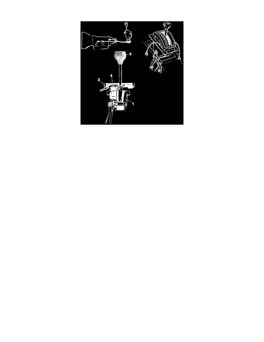
Gear Selector Mechanism
Mounted on the propeller shaft tunnel, the gear selector mechanism is operated by a lever which is locked in certain positions. A release button on
the lever must be pressed to select positions other than these.
The selector positions are P, R, N, D, 2 and 1. Both the selector lever and ratchet plate are pivot-mounted in the selector housing, which is bolted
to the body.
Since the lever and plate are also connected to the gearbox by the selector linkage, the mechanism follows the movements of the gearbox. The
main components of the mechanism are:
1. Selector housing bolted to body.
2. Gear selector lever attached to selector link on gearbox by a control rod.
3. Ratchet plate attached to gearbox housing by a reaction arm and strut linkage.
The mechanism incorporates a two-function switch (4) incorporating;
-
start-inhibitor contacts ensuring that the engine can be started only in positions P and N.
-
reversing light contacts operated in position R.
The gear selector knob is also provided with a switch for engaging and disengaging 4th gear.