
940 SE L4-2320cc 2.3L SOHC Turbo VIN 87 B230FT (1991)
Crankshaft Position/Engine Speed Sensor: Description and Operation
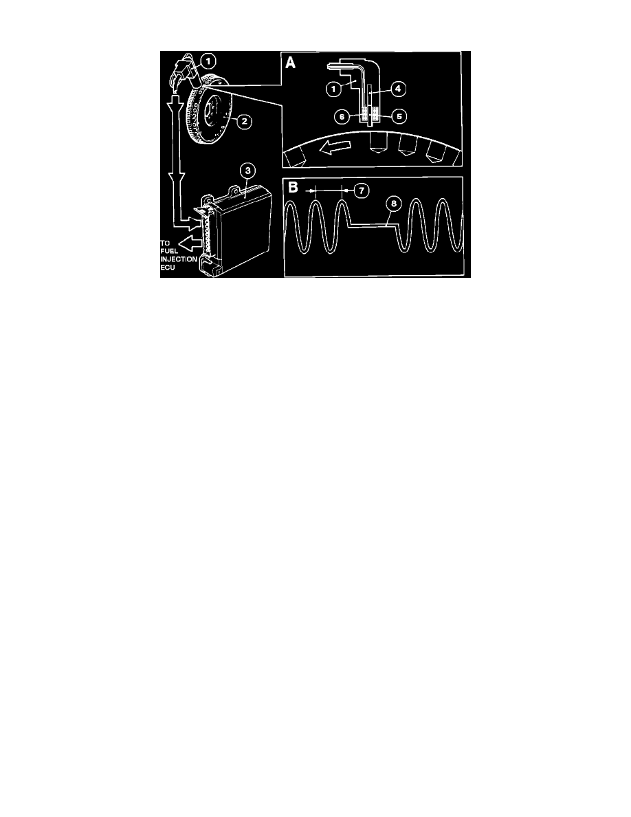
Crankshaft Position And Speed Sensor
PURPOSE
The input signal for crankshaft position and engine speed is generated by the crankshaft position/speed sensor.
The signal is processed by the ignition ECU (3). A modified signal is sent to the fuel injection ECU to determine the optimum air/fuel ratio to
meet the specific demands of the engine.
LOCATION
The sensor is mounted close to the flywheel (2) which is provided with a series of drilled holes or "windows" around the circumference.
CONSTRUCTION (A)
The sensor (1) consists of a permanent magnet (4), a pole tip (5) which concentrates a magnetic field at the end of the device and a coil (6). The
magnet creates a magnetic field which varies in strength depending on whether a hole or "window" is passing the tip.
OPERATION
Voltage is induced in the sensor as each "window" on the flywheel passes the tip. This voltage signal supplies the ignition ECU with a unique
electrical picture from which it can determine both crankshaft position and engine speed.
SIGNAL (B)
The frequency (7) of the signal is used to determine the engine speed.
To provide a reference signal for the crankshaft position, one "window" on the flywheel circumference is longer than the others. The ignition ECU
detects the crankshaft position by sensing the interruption in the signal (8) which occurs as the long "window" passes the sensor (90° BTDC). This
referance is used to determine the top dead center (TDC) position.