
S60 L5-2.4L VIN 64 B5244S6 (2003)
-
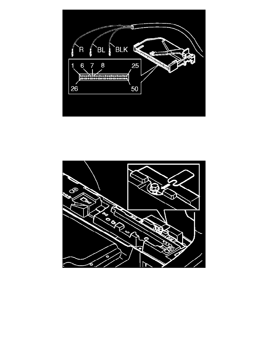
Connect the small cable harness from the control module to the connector for the accessory electronic module as follows:
-
Red (R) cable to terminal 6
-
Blue (BL) cable to terminal 7
-
Black (BLK) cable to terminal 8.
NOTE: The numerical markings can be found on the top and bottom of the black switch. However, the markings are extremely small so be
careful when installing the three cables.
-
Reinstall the black switch in the connector. Press the lock into place with the catch
-
Press the connector into the Accessory Electronic module. Secure using the black arm
-
Reinstall the Accessory Electronic Module. Secure any excess wiring
-
Reinstall the lock facing above the Accessory Electronic Module. Tighten the screw and the nut. Tighten to 10 Nm (8 lb.ft.).
-
Clean the visible surfaces on the sensor holders and sensors. Use a wet cloth (P/N 9192678). Allow to dry
-
Apply a thin layer of primer (P/N 9192679) over the sensors and the sensor holders. Allow to dry for at least 10 minutes
-
Spray the sensor holders and the sensors. Use the same colour as the car.
NOTE: Use a Volvo recommended paint. Apply a maximum of two layers of paint.
CAUTION: Too many layers of paint may result in partial or complete malfunction.