
S60 L5-2.4L VIN 64 B5244S6 (2003)
The following components are used for ignition control:
-
engine speed (RPM) sensor (7/25)
-
camshaft position (CMP) sensor (7/172-7/173)
-
mass air flow (MAF) sensor (7/17)
-
engine coolant temperature (ECT) sensor (7/16)
-
throttle position (TP) sensor on the electronic throttle unit (6/120)
-
knock sensor (KS) (7/24)
-
transmission control module (TCM) (4/28)
-
spark plugs with ignition coils (20/3-20/7)
-
brake control module (BCM) (4/16).
The engine control module (ECM) calculates the optimum ignition advance based on the software and information from the sensors. The engine control
module (ECM) cuts the current to the ignition coil mounted on the cylinder to be ignited and produces a spark.
During the starting phase the engine control module (ECM) produces a fixed ignition setting. When the engine has started and the vehicle is being
driven, the engine control module (ECM) calculates the optimum ignition setting, taking factors such as the following into account:
-
engine speed (RPM)
-
load
-
temperature.
The engine control module (ECM) analyses the signal from the knock sensor (KS) when the engine reaches operating temperature. If any of the cylinders
knock, the ignition is retarded for that specific cylinder until the knocking ceases. See also: Design See: Powertrain Management/Computers and Control
Systems/Description and Operation/Engine Management System/Design
The ignition then advanced to the normal position or until the knock recurs.
Before the transmission control module (TCM) changes gear, it sometimes transmits a torque limiting request to the engine control module (ECM). The
engine control module (ECM) then retards the ignition momentarily to reduce the torque, resulting in smoother gear changes and reducing the load on
the transmission. There are different ignition retardation levels depending on the signals from the transmission control module (TCM). The return signal
from the engine control module (ECM) to the transmission control module (TCM) confirms that the signal reached the engine control module (ECM).
The Brake Control Module (BCM) transmits information to the engine control module (ECM) about deviations in the drive line. The signal is used to
stop the diagnosis.
The engine misfires if the fuel does not ignite correctly.
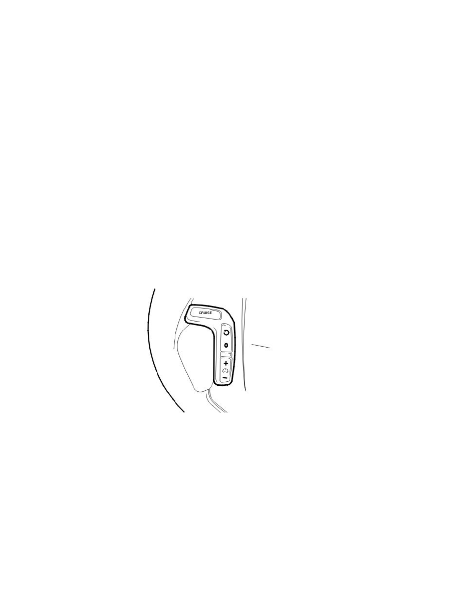
Regulating the cruise control
The cruise control function is an example of distributed functionality.
The following components are used when regulating the cruise control:
-
engine control module (ECM) (4/46)
-
steering wheel module (SWM) (3/254)
-
the cruise control control unit (3/4)
-
central electronic module (CEM) (4/56) (clutch pedal position)
-
brake control module (BCM) (4/16) (brake pedal position, speed signal)
-
driver information module (DIM) (5/1) (cruise control lamp)
-
transmission control module (TCM) (4/28)
-
electronic throttle unit (6/120)
-
stop lamp switch (3/9).
To activate cruise control the function must be switched on using the "CRUISE" button. A lamp lights up in the driver information module (DIM).
The driver activates the function by pressing the SET+ or SET- button. A message is then transmitted via the low speed side of the Controller area
network (CAN) to the central electronic module (CEM) which then transmits the message on via the high speed side of the Controller area network
(CAN) to the engine control module (ECM).
The engine control module (ECM) controls the throttle angle so that a constant speed is maintained using the vehicle speed signal from the Brake
Control Module (BCM). The transmission control module (TCM) also receives a message indicating that cruise control is active via the Controller area