
S60 L5-2.4L VIN 64 B5244S6 (2003)
Air Bag Control Module: Description and Operation
Input and Output Signals
Input And Output Signals
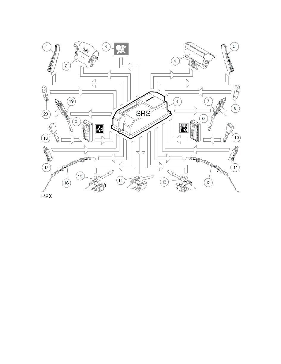
The illustration shows the control signals. In addition to these signals there is a repetitive diagnostic signal between the SRS module and all peripheral
units in the safety system. When the SRS system is started, (when the ignition is switched on), the SRS module performs a system test after which the
SRS indicator lamp in the combined instrument panel goes out. The SRS module then switches to monitor mode.
Components parts
1. SIPS module, driver's seat
2. Driver's airbag
3. SRS lamp
4. Passenger Airbag
5. SIPS, passenger seat
6. Side impact sensor, B-post on right-hand side
7. Seat belt tensioner, B-post on right-hand side
8. SRS module
9. Central electronic module (CEM)
10. Seat belt buckle, right front seat
11. Side impact sensor, C-post on right-hand side
12. IC, right-hand side
13. Seat belt tensioner, right-hand side in rear seat
14. Seat belt tensioner, rear center seat
15. Seat belt tensioner, left-hand side in rear seat
16. IC, left-hand side
17. Side impact sensor, C-post on left-hand side
18. Seat belt buckle, left front seat
19. Seat belt tensioner, B-post on left-hand side
20. Side impact sensor, B-post on the left-hand side.