
S60 L5-2.4L VIN 64 B5244S6 (2003)
Caution! Do not pull the drive shaft as the axial pinions cannot support large loads.
Note! If the hook is positioned at point (2) there is a risk of damaging the rubber boot on the ball joint.
Press the control arm down using lever 999 7076 Lever See: Tools and Equipment/999 7076 Lever. Position the hook at (1).
Align the spring strut in the control arm.
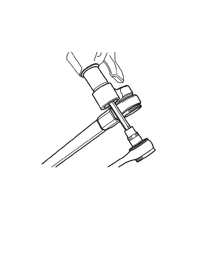
Installing the ball joint nut
Applies to vehicles with aluminum link arm
Caution! The ball joint pinion must not rotate. Use: 951 2927 Torx 40. Long version See: Tools and Equipment/951 2927 Torx 40. Long Version
as a counterhold to prevent damaging the rubber boot
Note! Use 999 5500 SOCKET UPPER NUT REAR SHOCK ABSORBER See: Tools and Equipment/999 5500 Socket Upper Nut Rear Shock
Absorber as a torque wrench.
Note! A counterhold is not required when angle tightening if the joint has been tightened to 50 Nm. The friction between the ball joint and
control arm is greater than between the nut and threads on the ball joint.
Install the 1 x nut.
Tighten according to step 1. See Tightening torque See: Steering/Specifications/Mechanical Specifications.
Use bevel protractor: 951 2050 BEVEL PROTRACTOR See: Tools and Equipment/951 2050 Bevel Protractor.
Angle-tighten according to step 2. See Tightening torque See: Steering/Specifications/Mechanical Specifications.
Rust protect the thread outside the nut.
Applies to vehicles with steel control arm