
S60 L5-2.4L VIN 64 B5244S6 (2003)
Caution! To ensure correct driving characteristics, the outer sleeve of the bushing must be flush with the flat milled side of the spindle (facing
forwards in the car).
Use special tool 999 5200 (2) to get the bushing into the correct position.
The yellow marking (1) on the bushing must be by the flat milled section on the hole for the bushing, i.e. forwards in the car (see arrow).
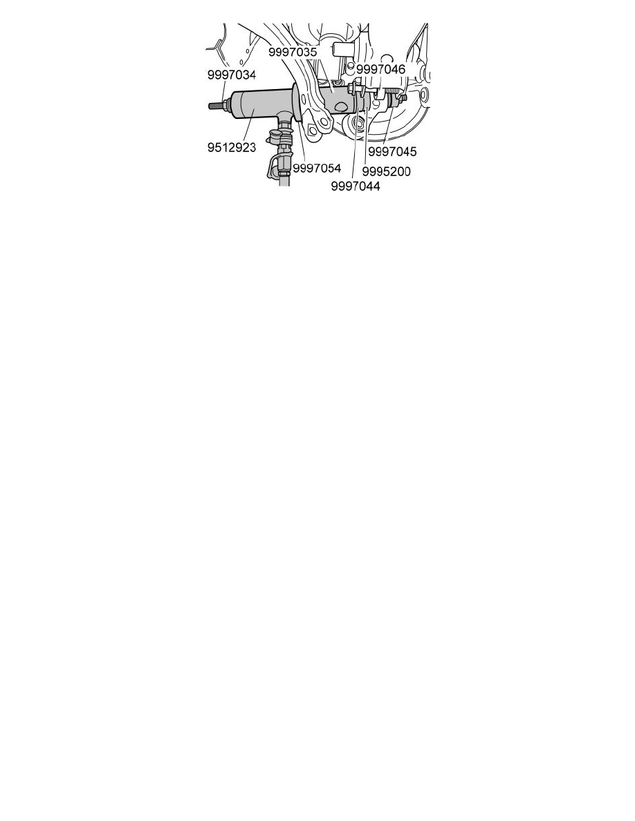
Install the hydraulic cylinder
Use tool 951 2923 Hydraulic hole cylinder See: Tools and Equipment/951 2923 Hydraulic Hole Cylinder with 999 7054 Adapter incl. 2x MC6C
M6X12 See: Tools and Equipment/999 7054 Adapter Incl. 2X MC6C M6X12 , 999 7046 Drift See: Tools and Equipment/999 7046 Drift , 999 7035
Sleeve See: Tools and Equipment/999 7035 Sleeve , 999 7044 Sleeve See: Tools and Equipment/999 7044 Sleeve , 999 7045 Drift See: Tools and
Equipment/999 7045 Drift , 999 7034 Connecting rod M12X400 See: Tools and Equipment/999 7034 Connecting Rod M12X400 and 999 5200
PUNCH See: Tools and Equipment/999 5200 Punch.
Note! Use 999 5200 PUNCH See: Tools and Equipment/999 5200 Punch to get the bushing into the correct position.
Press the bushing forwards in the direction of the vehicle.
Installing the wheel spindle, control arm and tie rod
Remove:
-
the screw for the control arm mounting
-
999 7046 Drift See: Tools and Equipment/999 7046 Drift.
Turn the spindle into position.
Install:
-
the screw for the control arm mounting. Use a new
-
the screw and nut for the tie rod. Use a new nut.
Note! Do not tighten the screw for the bushing mountings. This is carried out later when the rear suspension is in the normal position.
Release the tension from the tensioner and allow to hang freely.
Install:
-
the retaining strap and secure the lower control arm slightly against the jacking point
-
the screw for the tie rod. Use a new screw.
Tightening the stay and mountings
Press the suspension up to its normal position, see Tensioner, instructions for use, M66, TF-80SC, AW55-50/51SN, M56 See: Service and
Repair/Removal and Replacement/Tensioner, Instructions For Use.
Tighten:
-
both the mountings for the lateral link. Tighten to 80 Nm
-
the outer mounting for the tie rod. Tighten to 80 Nm
-
the control arm mounting. Tighten to 80 Nm.
Finishing
Install the wheel. See: Installing wheels See: Wheels and Tires/Wheels/Service and Repair.
Check/adjust the wheel alignment. See: Wheel alignment, checking / adjusting See: Alignment/Service and Repair.