
S60 L5-2.4L VIN 64 B5244S6 (2003)
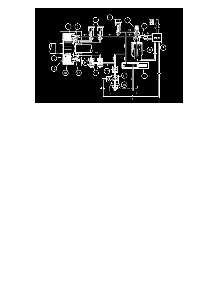
1. Cam disc
2. Rollers
3. Pressure valves
4. Pressure limiting valve
5. Control valve cover
6. Oil pressure and temperature sensor
7. Differential Electronic Module (DEM)
8. Control valve/axial solenoid
9. Accumulator
10. Oil screen
11. Electrical feed pump
12. Oil filter
13. Suction valves
14. Piston pump
15. Operating piston
16. Wet plate unit
17. Bearing
18. Springs.
The Active On-demand Coupling (AOC) can be described as a hydraulic pump.
The basic pressure is generated by the electronic feed pump. This pressurizes the annular pistons with oil so that they are pressed against the cam disc
via rollers. The annular piston generates a working pressure which is led to the operating piston via the pressure valve. This pressure creates a fixed
connection between the input and output shafts. The maximum pressure is limited by the pressure limiting valve. The difference in speed between the
input and output shafts is in proportion to the oil pressure fed to the annular pistons. A large difference between the input and output shafts results in
high oil pressure to the annular pistons. If the input and output shafts are at the same speed, the oil pressure to the annular pistons is less. The oil
pressure at the multiplate clutch is regulated by the control valve. The axial solenoid controls the control valve. A closed control valve gives maximum
pressure to the multi-plate clutch, resulting in maximum power transmission. An open control valve gives minimum pressure to the multi-plate clutch,
resulting in limited power transmission.
The accumulator maintains the basic pressure in the system. The oil filter keeps the fluid clean by filtering dirt and small particles which could damage
the system.
Diagnostic functions
General
The control module has a built-in diagnostic system, Volvo Diagnostic, which continuously monitors internal functions as well as input and output
signals.
Diagnostic trouble codes (DTCs)
A Diagnostic Trouble Code (DTC) is stored if the control module detects a fault. Should a fault disappear for any reason after being permanently
stored in the control module as a Diagnostic Trouble Code (DTC), the information remains stored in the control module.
Reading and erasing Diagnostic Trouble Codes (DTCs)