
S60 L5-2.4L VIN 64 B5244S6 (2003)
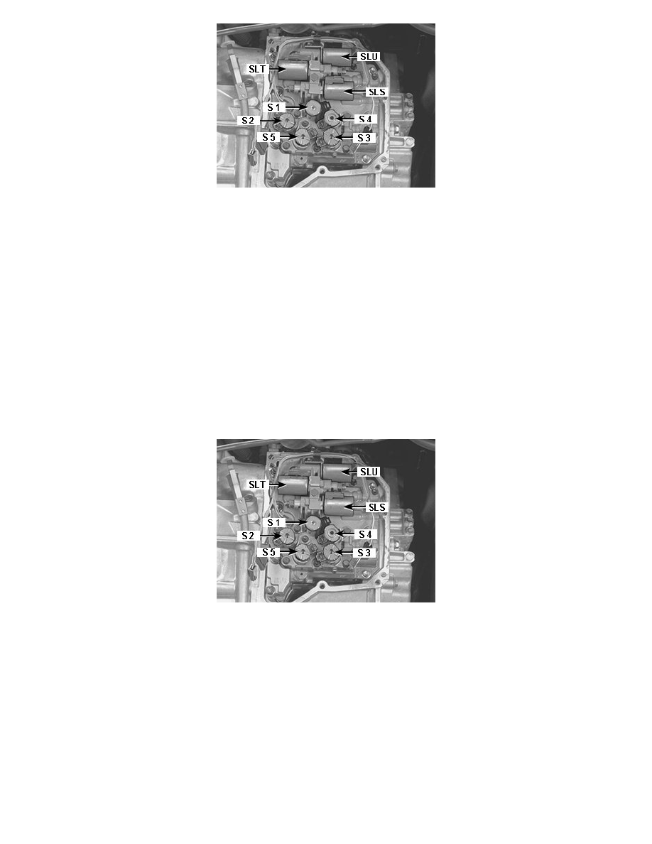
Location Of Components (Solenoids)
Note! Readings should be taken at approximately 20°C.
Solenoid S1
Measure the resistance between the pin in the solenoid connector and the transmission ground terminal.
Correct value: 12-16 ohms.
Solenoids S2-S5
Measure the resistance between the pin in the solenoid connector and the transmission ground terminal.
Correct value: 11-15 ohms.
If the resistance of any of solenoids S1-S5 is incorrect
Replace the solenoid. See Replacing solenoids S1-S5.
Checking the resistance of SLT, SLS and SLU
Location Of Components (Solenoids)
Note! Readings should be taken at approximately 20°C.
Solenoid SLT, SLS and SLU
Measure the resistance between both the pins in the solenoid connector.
Correct value: 5.0-5.6 ohms.
If the value of any of solenoids SLT, SLS and SLU is incorrect
Replace the control system. See Replacing the control system.
The control system is calibrated together with the solenoids.
Replacing solenoids S1-S5