
S70 L5-2.4L VIN 61 B5244S (2000)
Checking The Connectors
-
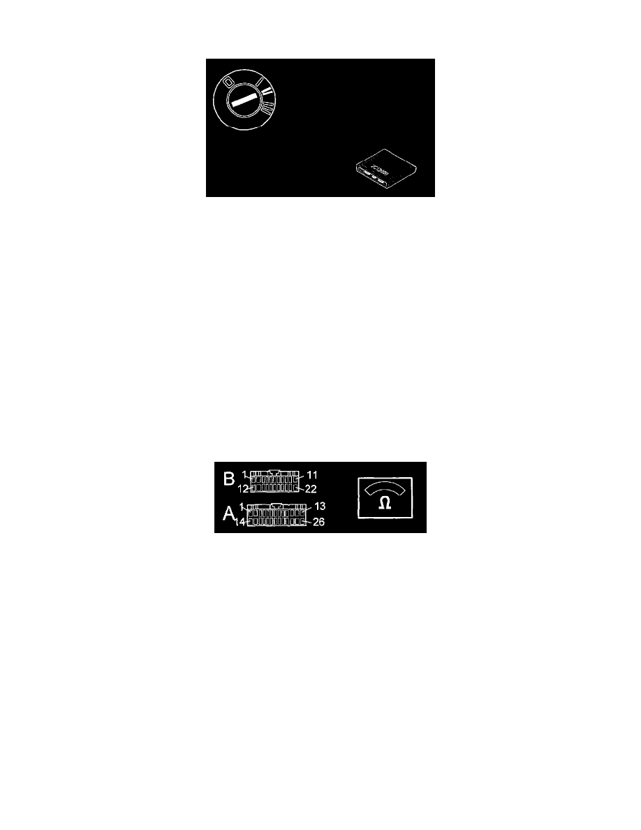
Disconnect indicator LED.
-
Check VGLA control module connector A and the indicator LED connector for contact resistance and oxidation, See: Diagnostic Trouble Code
Tests and Associated Procedures/Related Tests and Information/Checking Wiring and Terminals - Permanent Faults
-
Ignition on.
Activate the indicator LED.
The indicator LED should come on.
If the indicator LED lights, the fault has been caused by loose connections in the connectors.
Is the function OK?
Yes
-
Test complete
No
-
See: Checking Indicator LED/Checking For an Open-Circuit
Checking For an Open-Circuit
Checking For An Open-Circuit
Check cable between VGLA control module #A23 and indicator LED terminal 1 for an open-circuit according to Checking wiring and terminals -
Permanent faults and for a short-circuit to ground according to Checking wiring and terminals - Permanent faults. Also check the indicator LED
ground lead for an open-circuit according to Checking wiring and terminals - Permanent faults.
See: Diagnostic Trouble Code Tests and Associated Procedures/Related Tests and Information/Checking Wiring and Terminals - Permanent Faults
Were any faults found in the cables?
Yes
-
See: Checking Indicator LED/Verification
No
-
See: Checking Indicator LED/Replacing Component
Replacing Component
Replacing Component
Replace the indicator LED.
After performing this procedure See: Checking Indicator LED/Verification
Verification