
S70 L5-2.4L VIN 61 B5244S (2000)
^
Route wiring from the right side to the cable duct by the left wheel arch.
^
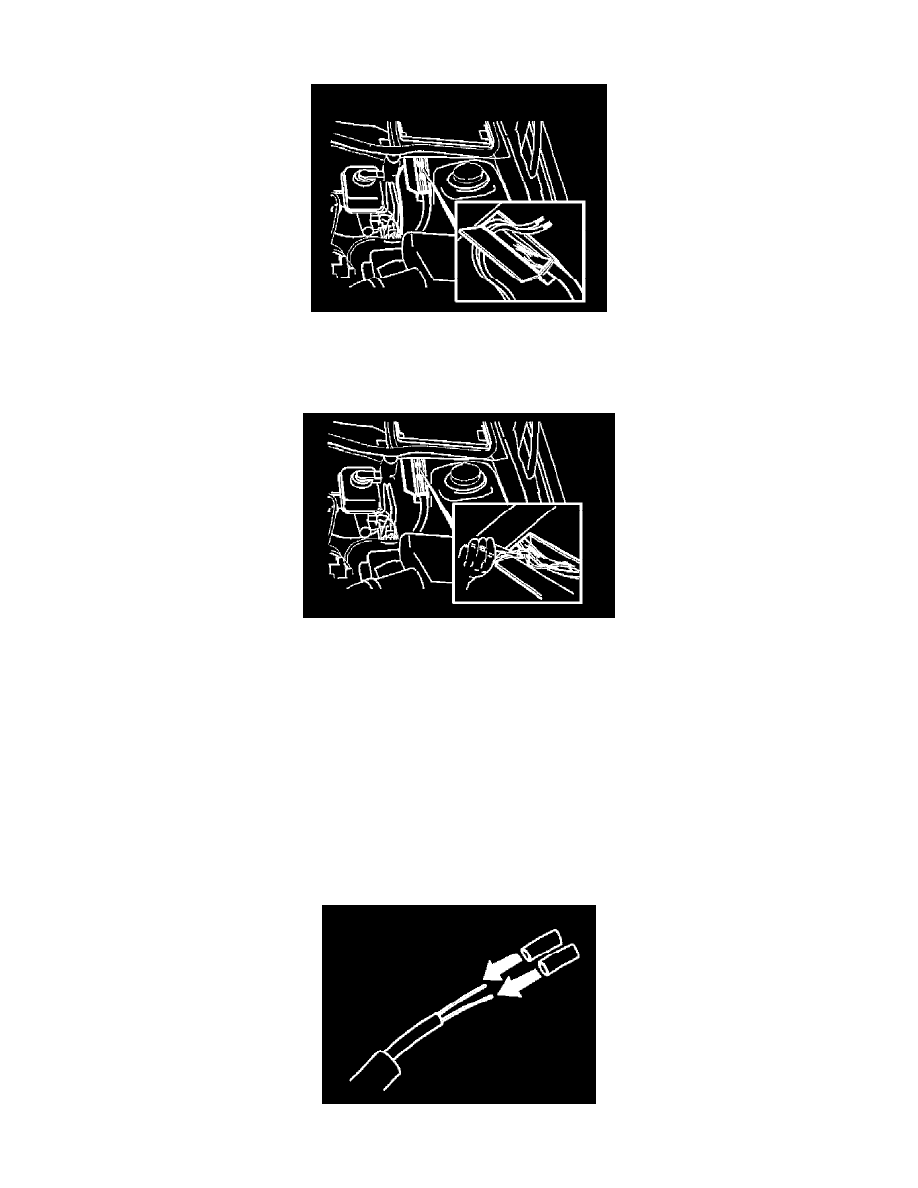
Open the cable duct.
^
Pull the new wiring into the cable duct through the opening at the firewall.
Note: Remember which cable comes from each side.
^
Locate two twisted cable pairs, 1 brown/white and 1 black/white.
^
Locate two twisted cable pairs, 1 brown and 1 black.
Caution: The two twisted cable pairs that go in the cable duct to the 25-pin ABS connector can be the same color (brown/black). It can be
difficult to determine which wheel a cable pair comes from. Therefore connect the cable pairs to the new ABS cables (A or B) one at a time
without crimping or soldering them as follows, and test with the Volvo Scan Tool (ST) according to (A21). Rotate a wheel and read the
instrument. Correctly connected cables will give a reading for the wheel which is rotating. Then splice/solder as follows.
Note: Cut off and splice one cable at a time.
^
Cut off the cables, one by one as close to the firewall as possible.
^
Splice the cables as follows: Black/white to black on the left-hand wiring. Then splice brown/white to brown on the left-hand wiring. Then splice
black to black on the right-hand wiring. Then splice brown to brown on the right-hand wiring.
Joining
^
Thread 2 heat-shrink tubes onto the new ABS sensor cables.