
S80 L5-2.5L Turbo VIN 59 B5254T2 (2004)
Powertrain Management/Computers and Control Systems/Testing and Inspection/Diagnostic Trouble Code Tests and Associated Procedures/Related
Tests, Information and Procedures/Checking Wiring and Terminals. Permanent Fault and short circuit to ground as described in Checking wiring and
terminals. Permanent fault See: Powertrain Management/Computers and Control Systems/Testing and Inspection/Diagnostic Trouble Code Tests and
Associated Procedures/Related Tests, Information and Procedures/Checking Wiring and Terminals. Permanent Fault.
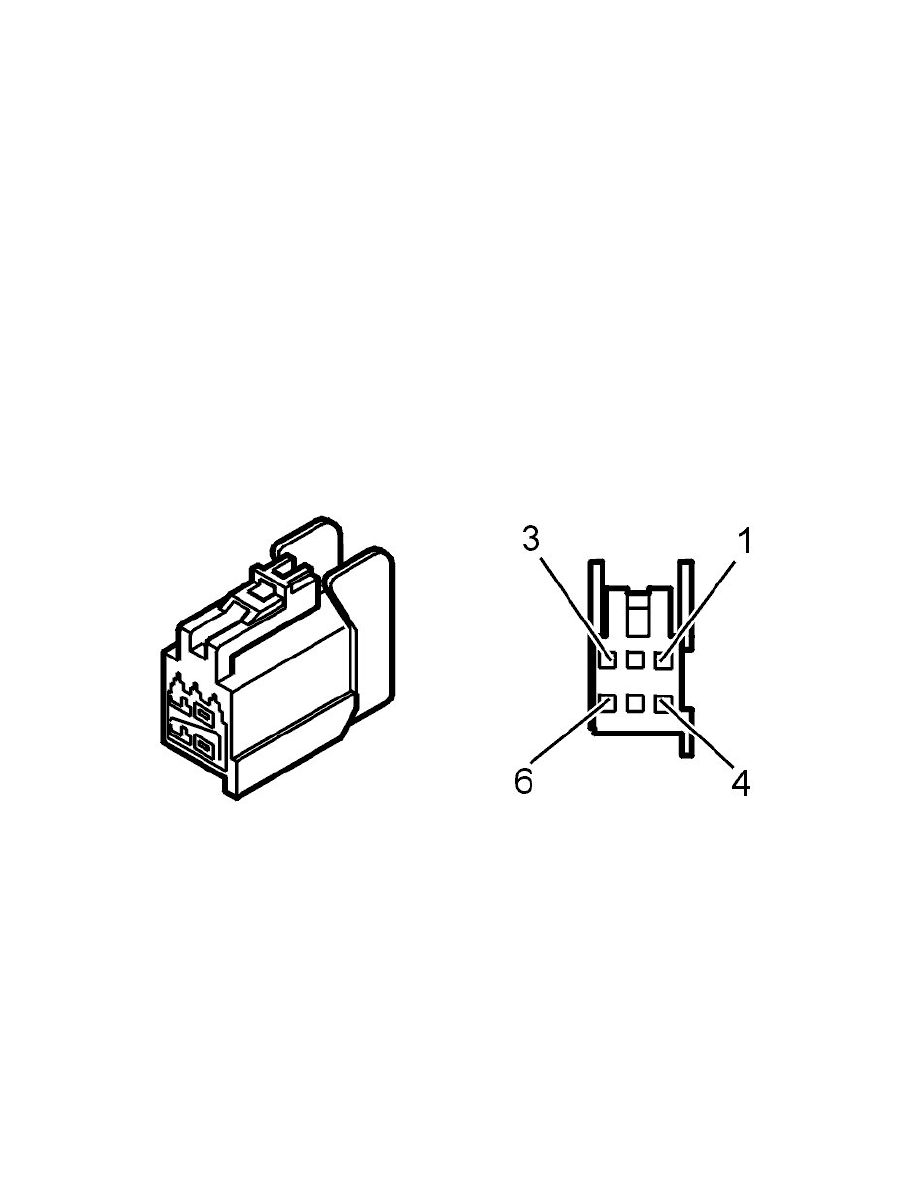
Check the wire between relay 2/75 3 and left and right head restraint solenoid connector 1 for an open circuit as described in Checking wiring and
terminals. Permanent fault See: Powertrain Management/Computers and Control Systems/Testing and Inspection/Diagnostic Trouble Code Tests and
Associated Procedures/Related Tests, Information and Procedures/Checking Wiring and Terminals. Permanent Fault and short circuit to ground as
described in Checking wiring and terminals. Permanent fault See: Powertrain Management/Computers and Control Systems/Testing and
Inspection/Diagnostic Trouble Code Tests and Associated Procedures/Related Tests, Information and Procedures/Checking Wiring and Terminals.
Permanent Fault.
Check the wire between the respective head restraint solenoid connector 4 and the ground point for an open circuit as described in Checking wiring and
terminals. Permanent fault See: Powertrain Management/Computers and Control Systems/Testing and Inspection/Diagnostic Trouble Code Tests and
Associated Procedures/Related Tests, Information and Procedures/Checking Wiring and Terminals. Permanent Fault.
Do the necessary corrective action.
Check the respective head restraint solenoid resistance. Too high a resistance value means an open circuit in the solenoid and too low a resistance value
indicates a short circuit in the solenoid. If there is a solenoid fault, replace the head restraint.
Hint: A fault-free head restraint solenoid has a resistance of 2.0 - 2.5 ohm. The resistance is most appropriately measured between the respective head
restraint solenoid connector 1 and 4.
Additional information:
-
To access relay/fuse box in the boot, see Integrated relay/fusebox cargo compartment/Rear electronic module (REM), replacing See:
Maintenance/Fuses and Circuit Breakers/Fuse Block/Service and Repair/Integrated Relay/Fusebox Cargo Compartment/Rear Electronic Module
(REM), Replacing.
-
For replacement of head restraint, see Outer head restraint .
-
For connection of test box, rear electronic module (REM), see Connecting the breakout box See: Body Control Systems/Testing and
Inspection/Pinout Values and Diagnostic Parameters/Connecting the Breakout Box/Connecting Breakout Box, Rear Electronic Module (REM).