
S80 L6-3.2L VIN 98 B6324S (2007)
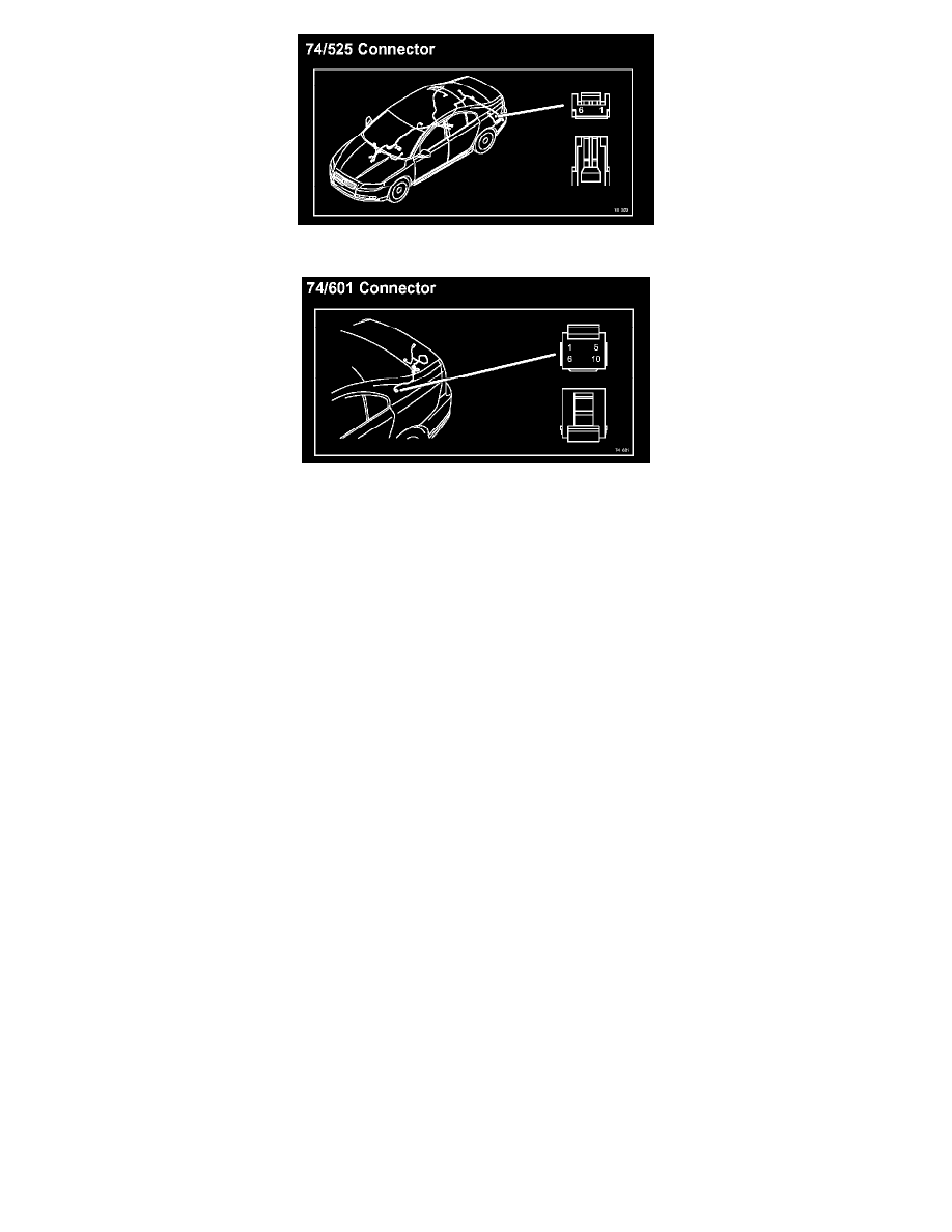
74/525 Connector
74/601 Connector
Wire Color Code and Other Abbreviations
Wire Color Code And Other Abbreviations
Groups
Group 23 = Fuel system
Group 26 = Cooling system
Group 27 = Engine controls
Group 32 = Generator and voltage regulator
Group 33 = Starting system
Group 35 = Lighting
Group 36 = Additional electrical equipment
Group 37 = Wiring and fuses
Group 38 = Instruments
Group 39 = Other
Group 43 = Transmission
Group 59 = Brake system
Group 64 = Steering
Group 83 = Doors and openings
Group 84 = Exterior decorative elements etc.
Group 85 = Interior equipment
Group 87 = Climate control system
Group 88 = Internal equipment
Ignition switch symbols
X
=
Accessories (audio position)
S
=
Powered upon insertion of key
15
=
Contact remains connected during start
15l
=
Contact is broken while starting
30
=
Constant power from the battery
50
=
Start
Countries/Markets
A
=
Austria
AUS
=
Australia