
S80 2.9 L6-2.9L VIN 94 B6294S (2000)
-
Check the cables visually. Use a voltmeter to take readings at various points in the circuit while operating switches and sensors.
The voltmeter reading depends on the circuit being tested and the positions of switches and sensors. Use the wiring diagram to determine the correct
voltage in the circuit.
Use an ohmmeter between the suspect cables to detect short-circuits between them.
The ohmmeter should read infinite resistance between cables not connected to each other in the circuit.
Shake the cable lightly and pull on connectors during measurement to locate the damage.
If the reading is not correct. Replace the cable
Loose connections (terminals)
Loose connections in terminals may be caused by oxidation of the pins and sockets, or by a faulty connection of a cable to its cable terminal.
Loose connections produce the same faults as an intermittent open-circuit in a cable.
Contact resistance and oxidation
In theory, the resistance across contacts, leads and terminals should be 0 [ohm]. However, there is always some resistance due to terminal oxidation.
If resistance is too great there will be function problems. The magnitude of the resistance before it causes a malfunction depends on the circuit load. A
guideline would be a few ohms.
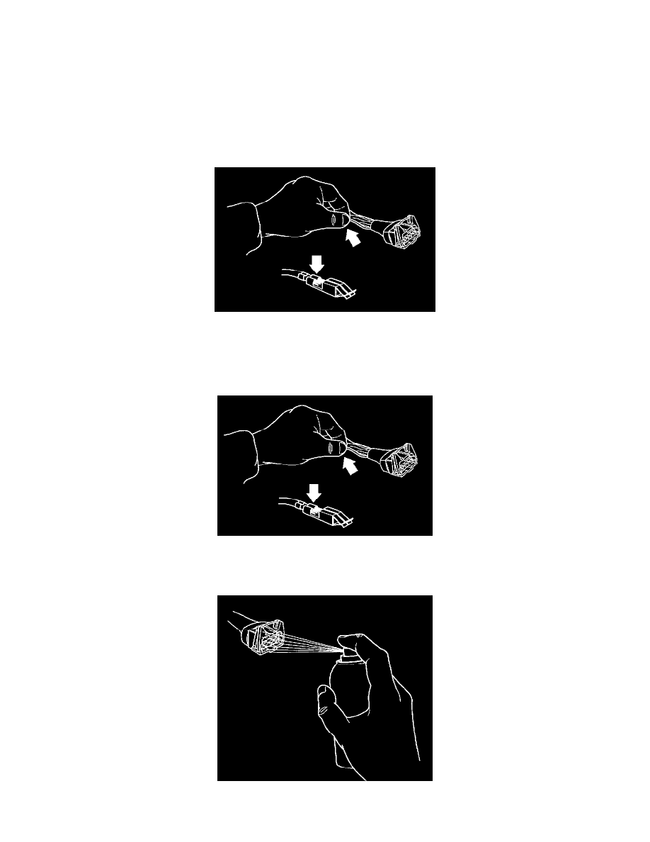
NOTE: Do not apply rust solvent spray or grease to the heated oxygen sensor (HO2S) or combined instrument panel connectors.