
S80 2.9 L6-2.9L VIN 94 B6294S (2000)
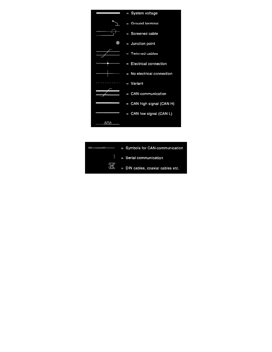
Explanation Of Symbols Fig. 1
Explanation Of Symbols Fig. 2
Table
Certain multi-point switches are described using a table, see the example below. The table is used to read off when the terminals are electrically
connected to each other.
Example. In position III, terminal 30 is connected to terminals 15A, S, and 50.
D. Junction points
The junction points are numbered. There is a list of the different junction points. It shows which other components the junctions points are joined to. The
locations are shown in Locations, Harness, "Routing of cable harnesses in the car". See: Locations/Harness Locations
E. Electrical distribution
Supply to the fuse is displayed in its entirety in Starting and Charging, Power and Ground Distribution, Diagrams, "Electrical distribution". See: Power
and Ground Distribution/Diagrams
F. Abbreviations
There are a number of abbreviations used in the book. These are explained in "Wire Color Code Identification and Other Abbreviations". See:
Diagrams/Diagram Information and Instructions/Wire Color Code Identification and Other Abbreviations
Example. R-W = Red-white
G. CAN-communication
Cables which are drawn as broken lines are displayed in their entirety in Powertrain Management, Computers and Controls Systems, Information Bus,
Diagrams, "Data communication". See: Powertrain Management/Computers and Control Systems/Information Bus
H. Components