
V40 L4-1.9L Turbo VIN 25 B4204T2 (2000)
The diagrams of the large complicated components are divided into sub-diagrams. These are designated 1(3), 2(3) and so on.
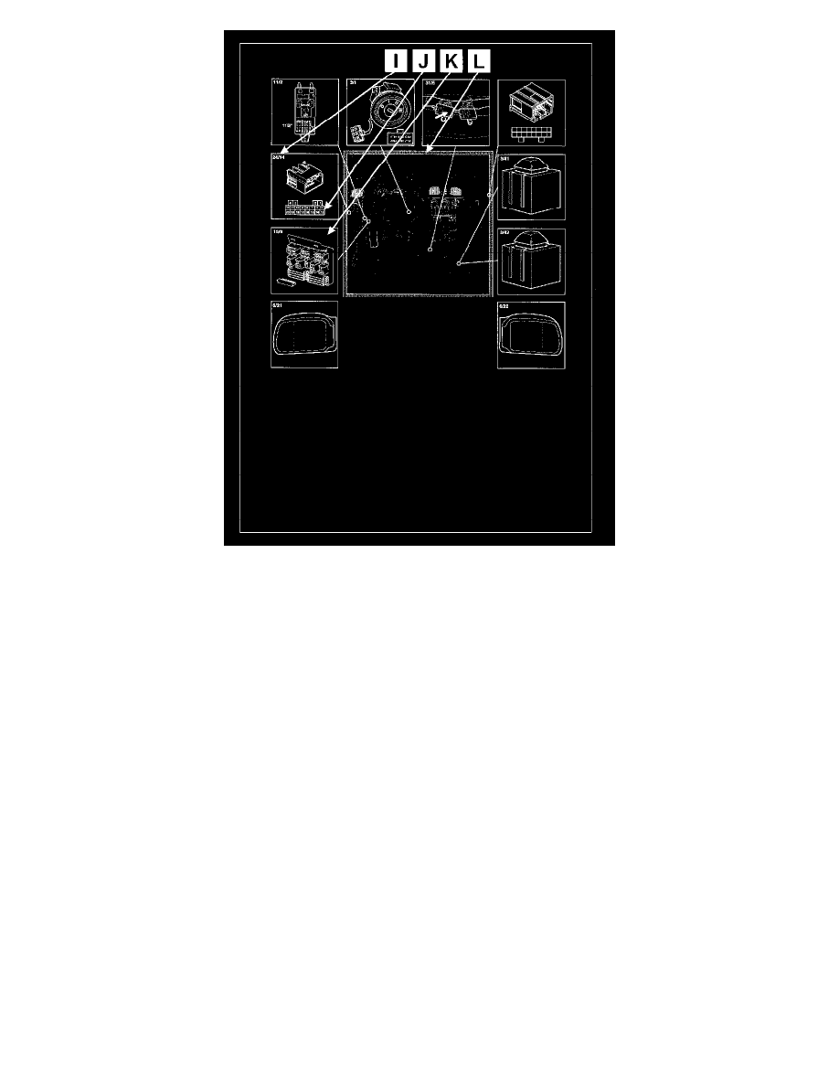
Battery (1/1), ignition switch(3/1) and central electrical unit (11B) in the passenger compartment are always at the top of the diagram.
The connection for this central electrical unit (J1, J14 and so on) are on the page Relay box in the passenger compartment
A
Fuses
The fuses are divided between the central electrical units. The fuses in the engine compartment start at 11A. The fuses in the passenger compartment start
at 11B. There are also larger fuses in the engine compartment. These are indicated in the diagram by thick lines.
B
Diagram
There are tables for certain components (the ignition lock for example) which display which terminals are electrically connected to each other at the
various switch positions.
C
Reference
Reference to a component that does not have any direct relevance to the open diagram.
D
Junction
This is a junction in the cable harness.
E
Control module
All control modules are gray. Any references to a control module are in gray blocks.
F
Connector
Connector with terminal number (24/xx is always a connector).