V40 L4-1.9L Turbo VIN 25 B4204T2 (2000)
Install the switch in reverse order
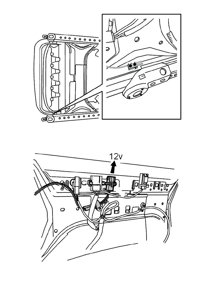
Note! The switch button (red) must be at the front.
-
Check the function of the switch by connecting 12 V to the connector on the plate

Install the switch in reverse order
Note! The switch button (red) must be at the front.
-
Check the function of the switch by connecting 12 V to the connector on the plate