
V40 L4-1.9L Turbo VIN 25 B4204T2 (2000)
Install:
-
The sensor. Finger tighten the mounting screws.
-
The rubber washer, the lock washer and the nut for the gear shift linkage rod.
Torque: 25 Nm.
Lock the nut with the washer.
Adjusting and checking
Adjust the gear-shift position sensor according to Checking and adjusting the gear-shift position sensor See: Transmission Position
Switch/Sensor/Adjustments.
Installation
Install:
-
The bracket for the dip stick pipe. Ensure that the O-ring is in position. Tighten the nut
Torque: 25 Nm
-
The lever on the gear shift linkage rod.
Torque: 16 Nm
-
The transmission cable on the lever with a washer and retaining clip. Apply a small amount of grease (P/N 1161241- 3) to the lever shaft journal.
If the transmission cable bracket was removed:
Install the bracket. Adjust the transmission cable according to Adjusting the transmission cable See: Automatic Transmission/Transaxle/Shift
Linkage/Shift Cable/Adjustments.
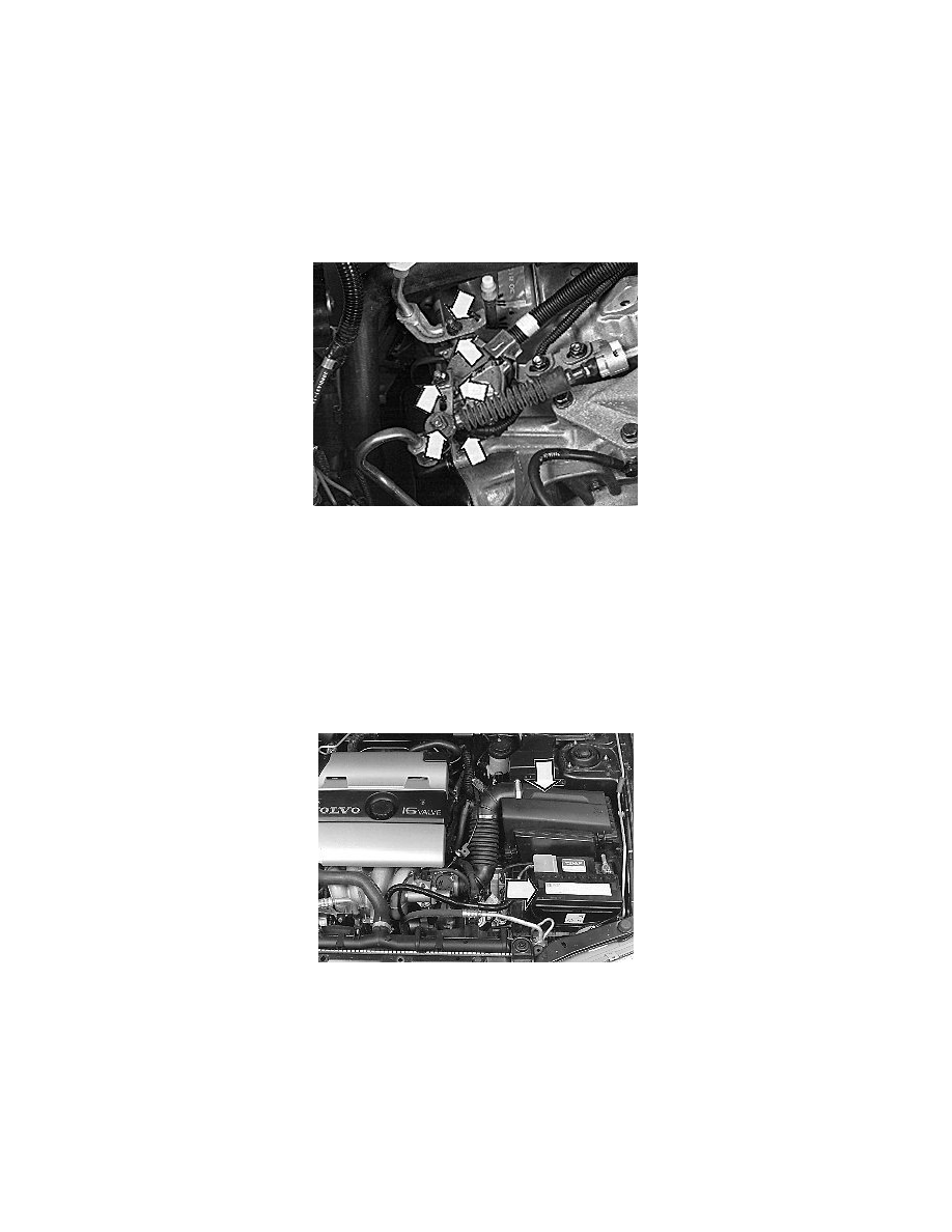
Installing engine compartment components
Install:
-
The battery shelf
-
The air cleaner (ACL) housing assembly, see Replacing the air cleaner (ACL) See: Engine, Cooling and Exhaust/Engine/Tune-up and Engine
Performance Checks/Air Cleaner Housing/Service and Repair/Removal and Replacement.
-
The battery
Checking diagnostic trouble codes (DTCs)
Check and erase any diagnostic trouble codes (DTCs).
Check the positions of the gear-shift position sensor. If it is not possible to use VCT 2000 as a handheld test tool, use the Volvo Scan Tool (ST) as the
test instrument instead. To connect the Volvo Scan Tool (ST), see Connecting the Volvo Scan Tool (ST) See: Heating and Air Conditioning/Testing and
Inspection/Scan Tool Testing and Procedures/Connecting the Volvo Scan Tool (ST).