
V70 L5-2.4L VIN 61 B5244S (2004)
VCT2000 and cable harness
-
Connect VCT2000 to the vehicle so that it is supplied with voltage. Test VCT2000 by selecting the system's self-test and VCT Test in the VIDA
main menu. If any malfunction is found according to the test, first replace the cable harness then the VCT2000, if the test still indicates a
malfunction.
-
If no malfunctions were found after troubleshooting according to above, try with a new cable harness and/or new VCT2000.
VIDA
-
If no malfunctions were found after troubleshooting according to above, try performing a complete system reset of VIDA.
Other information
-
Checking wiring and terminals See: Testing and Inspection/Component Tests and General Diagnostics/Checking Wiring and Terminals/Checking
Wiring And Terminals
Continue - Fault Found
------------------------
Checking communication errors, car model V70 (-00), V70 XC and S70/C70
Hint: Test the communication with another corresponding vehicle to decide if the malfunction is in the vehicle or in VIDA/VCT/cable harness. If the
communication works on another vehicle, the malfunction is in the vehicle.
Hint: For current information about each circuit and signals, see wiring diagram and signal description for each system.
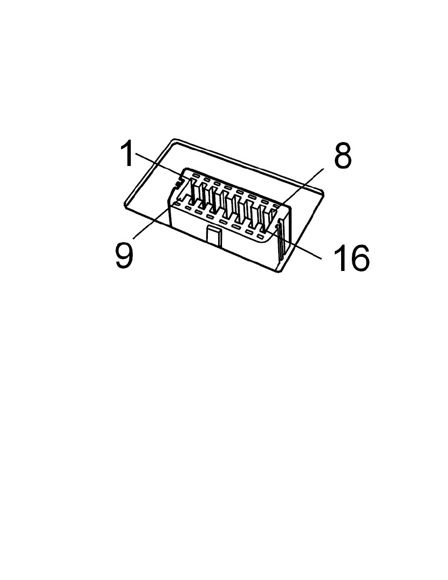
Diagnostic outlet
-
Check the voltage feed to diagnostic outlet #16. The voltage shall match battery voltage.
-
Check the cable for power ground and signal ground to diagnostic outlet #4 and #5.
Hint: When VCT2000 is connected to the diagnostic outlet (is supplied with voltage), the indicator diode shall be activated with a green light. Then the
indicator diode flashes quickly when communication takes place with a control module. In case of certain internal malfunctions on VCT2000 the
indicator diode is activated with a red light!
Communication cables
-
Check the communication cable (k-line) between diagnostic outlet #7 and the driver information module (DIM) #B4 and other connected control
modules for open circuit, short-circuit to ground and short-circuit to voltage.
Caution! In case of malfunction on this communication cable, communication cannot be established on the high-speed network. First
when communication takes place on this cable, the high-speed cables between the diagnostic outlet and driver information module (DIM)
are connected to the high-speed network in the vehicle. This is controlled via a relay in the driver information module (DIM).
-
Check communication cables between diagnostic outlet #6/#14 and the driver information module (DIM) #A19/#A20 for open circuit,
short-circuit to ground and short-circuit to voltage according to references above.
-
Also check the communication cables for thehigh-speed networkbetween the driver information module (DIM) and the other connected control
modules according to troubleshooting above.
Communication cable for cruise control as own system (not integrated)