
V70 2.4 L5-2.4L VIN 61 B5244S (2001)
Permanent fault See: Testing and Inspection/Component Tests and General Diagnostics/Checking Wiring and Terminals/Checking Wiring and
Terminals. Permanent Fault. Check for a short-circuit to ground according to Checking wiring and terminals. Permanent fault See: Testing and
Inspection/Component Tests and General Diagnostics/Checking Wiring and Terminals/Checking Wiring and Terminals. Permanent Fault.
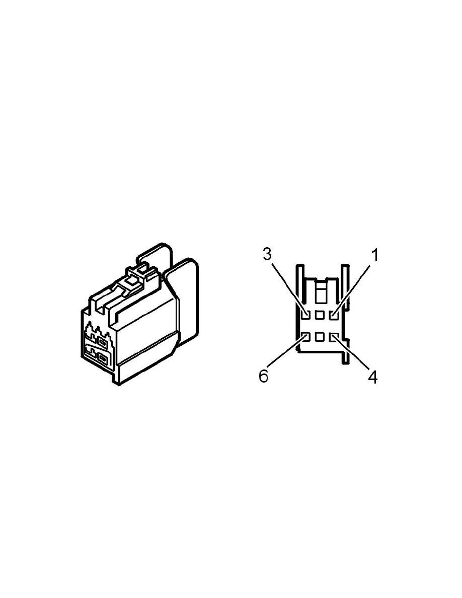
Check the cable between relay 2/75 terminal #3 and the left and right head restraint solenoid connector terminal #1. Check for an open-circuit according
to Checking wiring and terminals. Permanent fault See: Testing and Inspection/Component Tests and General Diagnostics/Checking Wiring and
Terminals/Checking Wiring and Terminals. Permanent Fault. Check for a short-circuit to ground according to Checking wiring and terminals. Permanent
fault See: Testing and Inspection/Component Tests and General Diagnostics/Checking Wiring and Terminals/Checking Wiring and Terminals.
Permanent Fault.
Check the cable between connector terminal #4 for each of the head restraints and the ground terminal for an open-circuit according to Checking wiring
and terminals. Permanent fault See: Testing and Inspection/Component Tests and General Diagnostics/Checking Wiring and Terminals/Checking Wiring
and Terminals. Permanent Fault.
Remedy as necessary.
Check the resistance of each head restraint solenoid. Too high resistance indicates an open-circuit in the solenoid. Too low resistance indicates a
short-circuit in the solenoid. Replace the head restraint in the event of a fault in the solenoid.
Hint: The resistance in a correct head restraint solenoid is 2.0 - 2.5 ohms. The resistance should be measured between connector terminals #1 and #4 on
each of the head restraint solenoids.
Other information:
-
To access the integrated relay / fusebox in the cargo compartment, see Relay/fuse box cargo compartment/Rear electronic module (REM),
replacing See: Maintenance/Fuses and Circuit Breakers/Fuse Block/Service and Repair/Integrated Relay/Fusebox Cargo Compartment/Rear
Electronic Module (REM), Replacing.
-
To replace the head restraint, see Outer head restraint See: Service and Repair/Outer Head Restraint.
-
To connect the breakout box to the rear electronic module, see Connecting the breakout box See: Body Control Systems/Testing and
Inspection/Pinout Values and Diagnostic Parameters/Connecting the Breakout Box.