
V70 2.4 L5-2.4L VIN 61 B5244S (2001)
Steering Gear: Description and Operation
Design
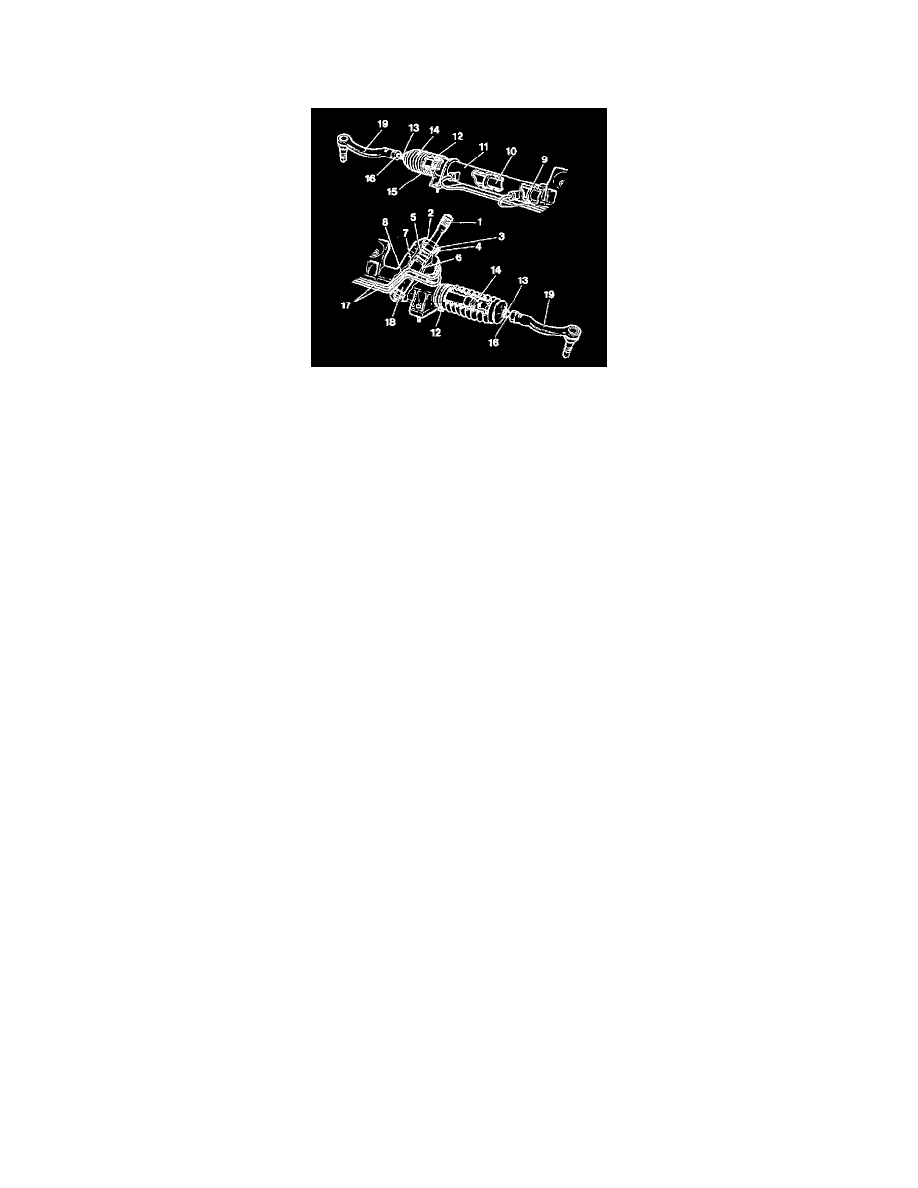
Legend
1. Input shaft pinion
2. Dust cover
3. Seal
4. Roller bearing
5. Rotary valve
6. Seal
7. Sliding bearing
8. Actuating piston
9. Rack seal
10. Rack
11. Cylinder pipe
12. Clamp
13. Clip
14. Protective bellow
15. Sliding bearing
16. Tie rod
17. Oil pipe
18. Gear drive (pinion)
19. Outer ball joint
20. Piston
21. Steering gear housing
The steering gear is of the rack and pinion type with the mechanical and servo assisted elements combined in one module. This means that even if the
servo assistance was lost the mechanical steering would remain.
The mechanical element consists of the gear drive (18), steering rack (10) and tie rods (19).
The gear drive is carried by a journey bearing (7) and a roller bearing in the steering gear housing. The input shaft is carried in a roller bearing (4).
The right end of the steering rack is supported in a bearing.
The rack is actuated in the housing by the gear drive (18) and spring-loaded pre-tensioning piston.
A cylinder pipe (11) is secured to the steering gear housing (21). This pipe also acts as the operating cylinder for the power steering piston.
Oil from the power steering pump is controlled in the valve housing. This is integrated with the steering gear housing.
The steering gear input shaft is connected to the gear drive with a torsion bar.
The steering gear is connected to the tie rods that have ball joints at the ends. The inner ball joints are inside rubber boots and fastened directly onto
the steering rack.
The outer ball joints are permanently greased and fixed onto the tie rods.