
XC60 FWD L6-3.2L VIN 96 B6324S2 (2010)
Trailer Lighting Module: Pinout Values and Diagnostic Parameters
Connecting Breakout Box, Trailer Module (TRM)
Connecting the breakout box
Special tools:
951 1428 Breakout box See: Tools and Equipment/951 1428 Breakout Box
951 2888 16-pin AUD adapter See: Tools and Equipment/951 2888 16-Pin AUD Adapter
951 1508 Adapter 10-7-5 pin See: Tools and Equipment/951 1508 Adapter 10-7-5 Pin
Caution! Avoid touching control module connector pins and corresponding cable harness connectors. There is a risk of electrostatic discharge,
which could damage the control module. Relieve any charge on yourself and the tools to be used by holding the metal part of the tool and
touching part of the body just before starting work.
General information
Visually check the connectors to ensure that the male and female terminals are not damaged and that the cables for the female halves are properly
connected.
The breakout box is designed to facilitate reading off control module output and input signals when the control module is connected as well as resistance
of cables and components when the control module is disconnected. Using a breakout box reduces the risk of unintentionally short-circuiting cables or
damaging connector pins.
Connecting the breakout box
-
Ignition off
-
To expose the connectors for the trailer module (TRM):
Connect breakout box 951 1428 Breakout box See: Tools and Equipment/951 1428 Breakout Box to the adapter.
Trailer Module (TRM)
-
Connect adapter 951 2888 16-pin AUD adapter See: Tools and Equipment/951 2888 16-Pin AUD Adapter to the control module connector C1.
-
Connect adapter 951 1508 Adapter 10-7-5 pin See: Tools and Equipment/951 1508 Adapter 10-7-5 Pin to the control module connector C2.
-
For connector C1, terminals #C1:1 - #C1:2 correspond to terminals #31 - #32 on the breakout box.
-
For connector C2, terminals #C2:1 - #C2:5 correspond to terminals #22 - #26 on the breakout box.
Signal Specification, Trailer Module (TRM)
Signal specification
General
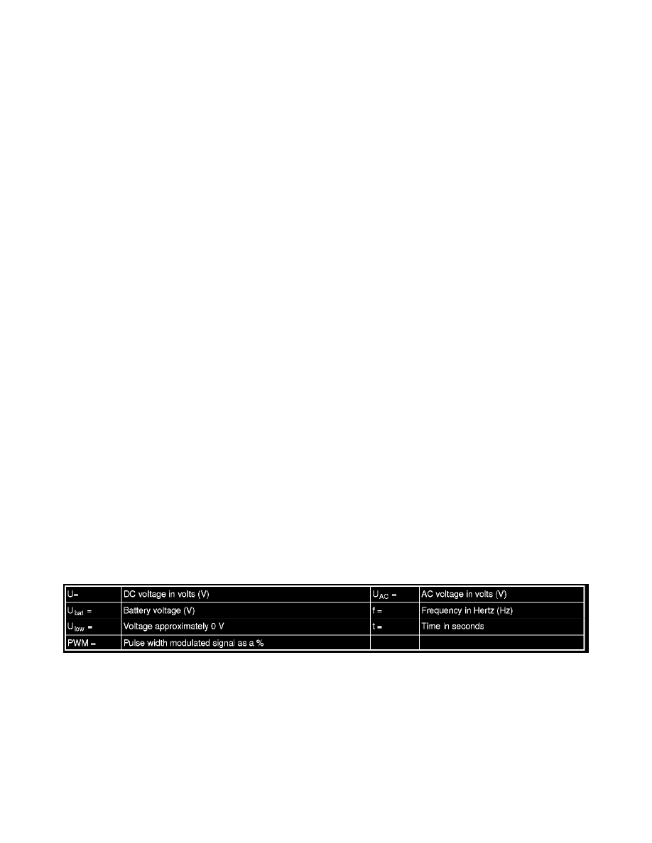
All the values given below are between the terminals stated in column 1 and terminal #C2:4 in column 2 (power ground).
Note! It is important to connect the breakout box and check the ground terminals before taking readings.