
XC70 AWD L6-3.2L VIN 98 B6324S (2009)
Headlamp Control Module: Description and Operation
System Overview
System overview
Control module
The primary task of the headlamp control module (HCM) is to manage the functions of:
-
Automatic headlamp levelling (vehicles with Bi-Xenon lamps)
-
Active headlamps (vehicles with active headlamps only)
The control module is mounted on a bracket toward the cowl panel in the cold zone between the engine compartment and passenger compartment. The
entire control module is removed from the vehicle upon replacement.
The headlamp control module (HCM) communicates both with directly connected components, and with other control modules via CAN communication.
The control module checks activations and input and output signals using an integrated diagnostic system A diagnostic trouble code is generated if the
control module detects a fault. In certain cases the control module replaces the faulty signal with a substitute value.
Any diagnostic trouble codes are stored in the relevant control module memory. The data can be read off using a diagnostic tool.
If the control module detects a fault, it stores a diagnostic trouble code in its internal memory. A number of values that were frozen at the time the fault
occurred are stored at the same time. Depending on the severity of the fault, certain functions may be partially or completely disengaged. A warning
lamp lights in the driver information module (DIM) to inform the driver that a fault has occurred. A warning or information text will also be shown in the
display in the driver information module (DIM). If the vehicle is equipped with active headlamps, the LED in the active headlamp button will flash. The
text displayed is determined by the type of fault. Diagnostic trouble codes and frozen values (additional diagnostic trouble code information) can be read
off using the diagnostic tool via the data link connector in the vehicle.
Ignition switch position II can be activated to check that the headlamp control module (HCM) is supplied power and is grounded. If the headlamps make
a reference sweep, the headlamp control module (HCM) is receiving power.
For further information, also see Signal specifications.
Signals
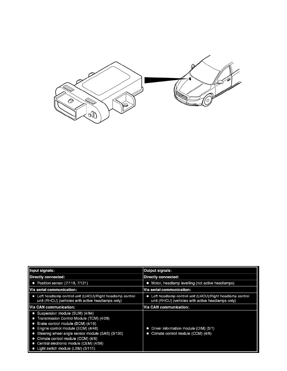
The table below summarizes the input signals to and output signals from the headlamp control module (HCM). The signal types are divided into directly
connected signals, serial communication and CAN communication. The illustration below displays the same information with the Volvo component
designations.