
XC90 L5-2.5L Turbo VIN 59 B5254T2 (2004)
Hydraulic Control Assembly - Antilock Brakes: Service and Repair
Hydraulic unit, replacing
Note! As the illustrations in this service information are used for different model years and/or models, some variation may occur. However, the
essential information in the illustrations is always correct.
Preparation
Remove the battery lead. See Battery, disconnecting See: Starting and Charging/Battery/Service and Repair/Procedures/Battery, Disconnecting
Warning! The hydraulic unit must not be opened under any circumstances. Reassembling it requires special equipment and facilities.
Note! An hydraulic unit for ABS has only eight valves while a unit for ABS and STC (stability and traction control) has ten valves. The method
for replacing the unit is the same for both types. Check thoroughly when installing the new unit that the unit is the correct type.
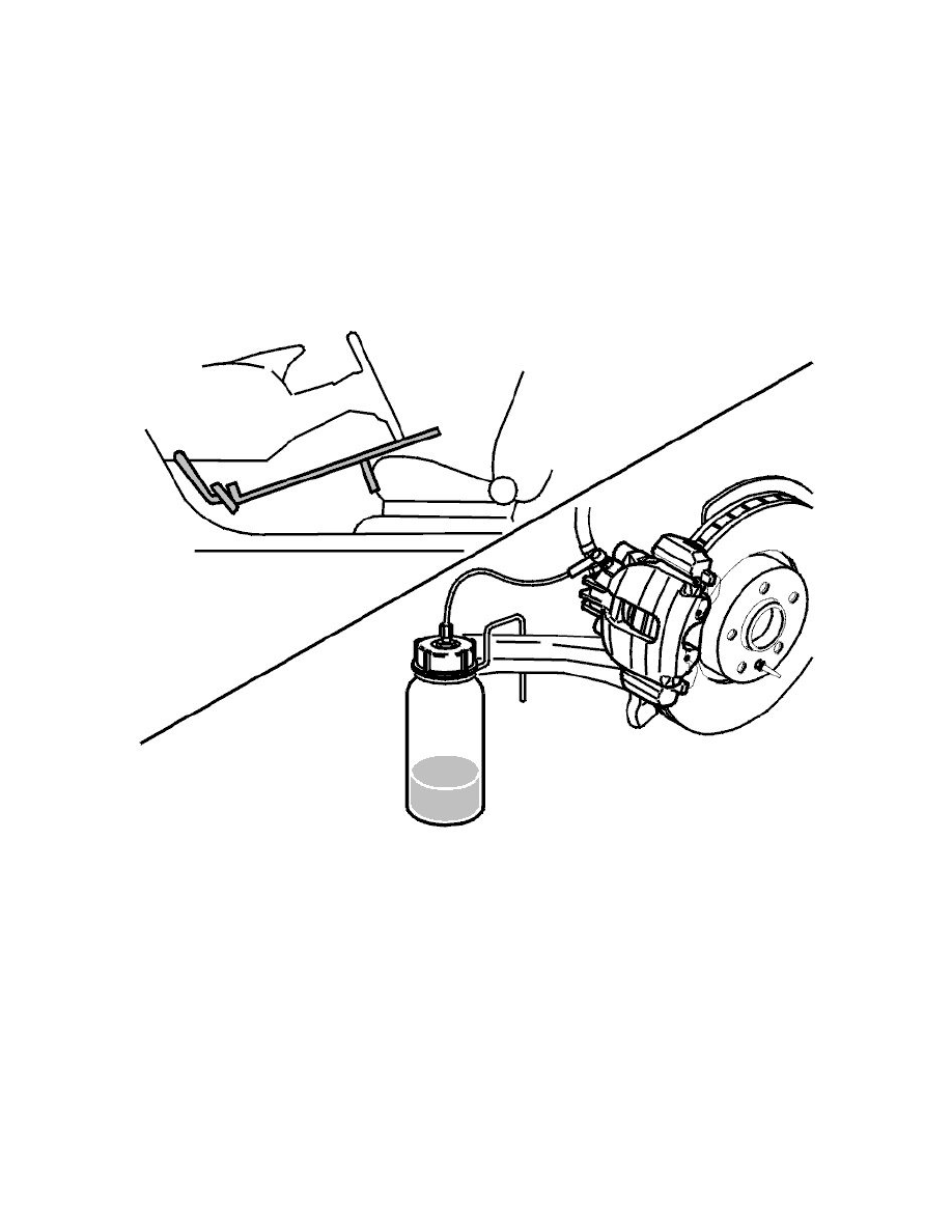
Secure the pedal in the depressed position.
Use a pedal jack.
Remove the protective cap from the bleed nipple at the left front wheel.
Install a plastic hose on the nipple. Open the bleed nipple.
Collect the brake fluid in a container (bottle).
Shut the bleed nipple.
Removing the brake pipe for the master cylinder/ABS unit
Remove the brake pipe between the master cylinder and the ABS hydraulic modulator. See Brake pipe master cylinder/ABS unit, replacing See:
Hydraulic System/Brake Hose/Line/Service and Repair/Brake Pipe Master Cylinder/ABS Unit, Replacing
Removing the ABS hydraulic modulator