
XC90 AWD L5-2.5L Turbo VIN 59 B5254T2 (2005)
Alternator: Description and Operation
Function
Function
General
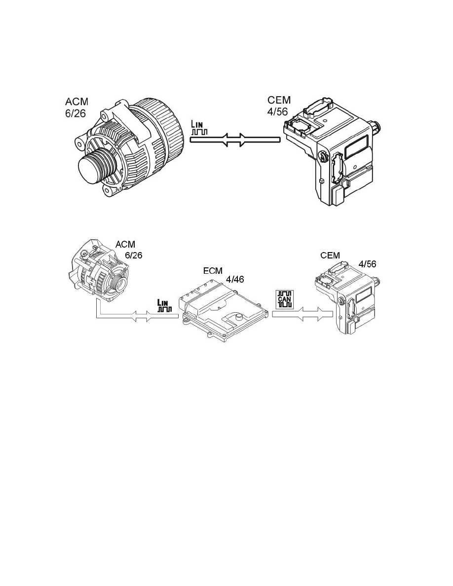
The above illustrations depict the two different types of connections for the alternator's regulator.
Output voltage from the generator (GEN) is calculated from the calculated battery temperature in order to charge the battery fully. The central electronic
module (CEM) calculates the battery temperature using the outside temperature. The outside temperature is obtained from the outside temperature
sensor.
See also Design and Function, Engine control module (ECM).
The Rear electronic module (REM) checks the voltage on the battery and transmits the value out on the CAN network. The value is used in the Central
electronic module (CEM), among others, for diagnosing the charging function.
Charging
When the ignition key is in position II (or III), the central electronic module (CEM) sends information to the charge regulator (also known as the
alternator control module (ACM)) either directly or via the engine control module (ECM).
The regulator directs current to the excitation winding rotor and is then grounded via the regulator. When the current travels through the rotor a magnetic
field is formed around the rotor. When the engine is started and the rotor begins to rotate, the magnetic field also rotates and then produces alternating
current in the stator windings.
Alternating current is rectified when it passes the diodes and is then fed to the electrical system of the vehicle. The voltage obtained from the stator
winding also passes to the regulator via the rectifier and affects the control functions.
The desired charge voltage (desired value), based on factors such as calculated battery temperature, is sent from the central electronic module (CEM) to
the charge regulator either directly or via the engine control module (ECM). The regulator then controls so that the desired voltage is obtained by the
battery.
The charge indicator lamp in the combined instrument panel is controlled by the driver information module (DIM) via signals from the controller area
network (CAN).
Current limiting