
XC90 AWD L6-2.9L Turbo VIN 91 B6294T (2004)
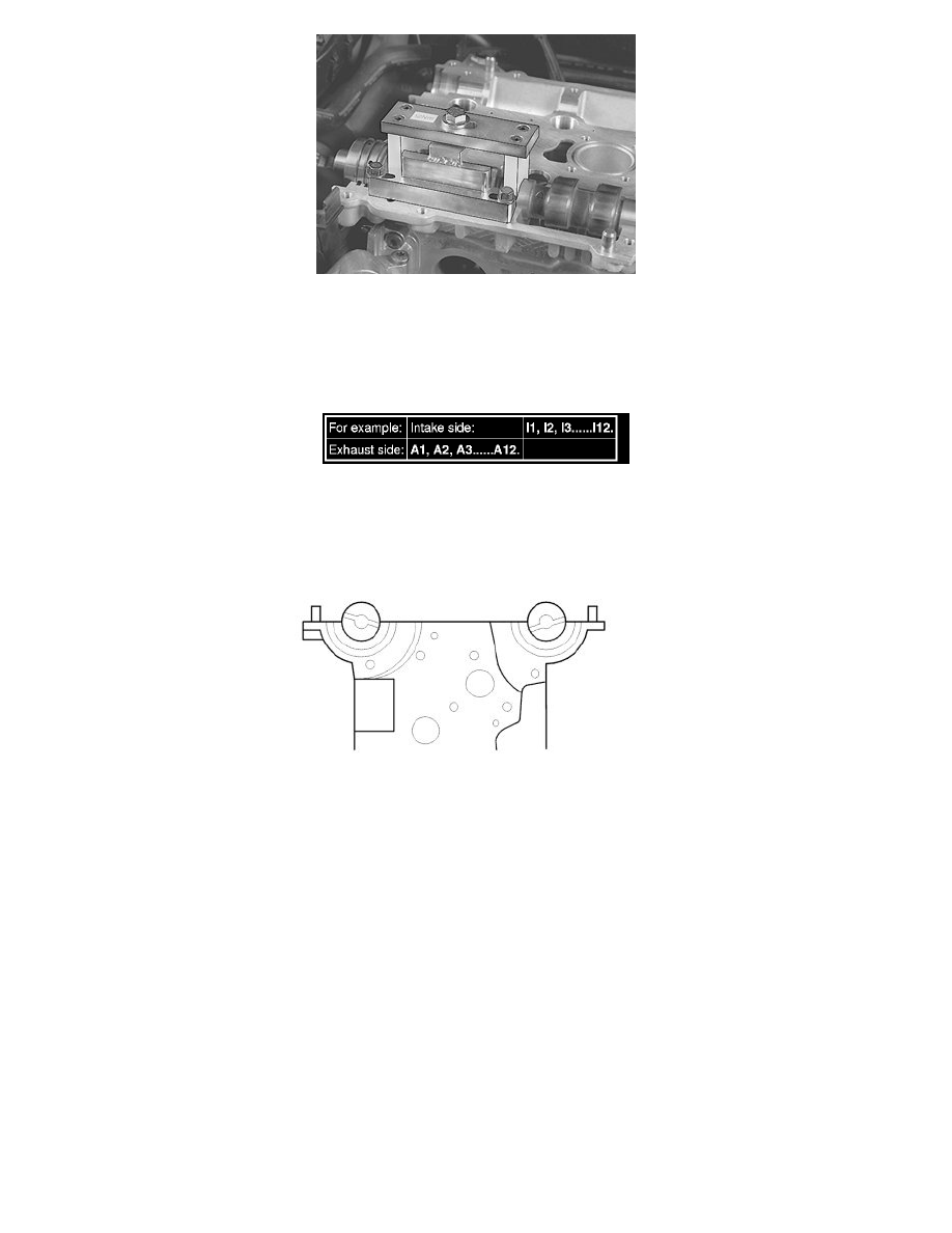
Remove
-
the press tool 999 5765
-
the camshaft
-
the valve lifters.
Note! Carefully mark the valve lifters so that exact reinstallation can be carried out.
Repeat the procedure for measuring the valve clearance for all cylinders on both the intake and exhaust sides. See Checking the valve clearance.
Installing valve lifters and camshafts
Note! For tightening torques not in the text, see Tightening torque, B6324S See: Engine, Cooling and
Exhaust/Engine/Specifications/Mechanical Specifications/Tightening Torque.
Lubricate the valve guide wells.
Install all the valve lifters.
Lubricate the camshaft bearing seats and the upper sides of the valve lifters.
Position the intake camshaft. Ensure that the groove at the rear edge of the camshaft is above an imaginary center line.
Position the exhaust camshaft. Ensure that the groove at the rear edge of the camshaft is below an imaginary center line.
Applying liquid gasket