
XC90 AWD L6-3.2L VIN 98 B6324S (2007)
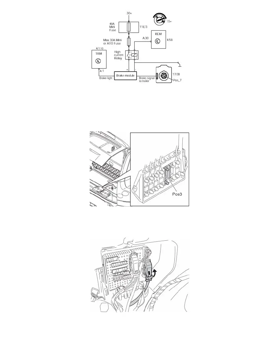
The image with wiring diagram shows the principle of electric brake connection.
The system must be fused with quick-acting fuse, maximum 30A, and controlled with relay, see diagrammatic illustration. Use Maxi fuse (P/N 9441158),
quick-acting fuse max. 30A by ATO (P/N 966331) or Mini (P/N 8470580) type. A separate holder must be used for these.
Note! Installation of equipment for the electric brakes must be carried out according to the supplier's instructions. Volvo takes no responsibility
for such equipment.
-
Obtain positive feed (30+) from position 3 in the main fuse box, which is located beside the battery. Insert a 40A Midi fuse in the holder (P/N
9441937).
Connection of relay control to "Ignition on" in the rear electronic module (REM)
-
Press in the catch on the front black connector in the cargo compartment fuse holder. Turn up the lock arm as far as possible and pull out the
connector.