XC90 AWD L6-3.2L VIN 98 B6324S (2007)
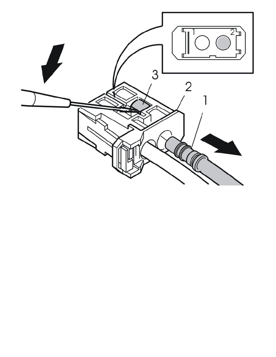
Open the catches (3) using a screwdriver.
Pull out the ferrule (1). Make a note of its location.
Disassembling the combined connector (optic and electrical conductor) (1)

Open the catches (3) using a screwdriver.
Pull out the ferrule (1). Make a note of its location.
Disassembling the combined connector (optic and electrical conductor) (1)