
XC90 AWD L6-3.2L VIN 98 B6324S (2007)
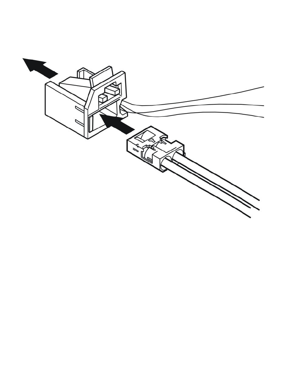
Assembling the combined connector (2 optic and 4 electrical conductors)
Install the ferrule. See Assembling the connector.
Press the inner section into place in the combined connector.
Finishing work
Check the repair. See Optical wiring harness check See: Wiring/Optical Wiring Harness Check.
Joining the Cables
Joining the cables
Connecting
See information about SRS cables: Refer to: Cable harness SRS system, repair See: Restraint Systems/Air Bag Systems/Air Bag/Air Bag
Harness/Service and Repair/Procedures
Perform battery disconnection. Refer to: Battery, disconnecting See: Starting and Charging/Battery/Service and Repair/Procedures/Battery,
Disconnecting
See information about cable terminals surface treatment. Refer to: Cable terminals surface treatment See: Power and Ground Distribution/Wiring
Harness/Service and Repair/Cable Terminals Surface Treatment