
XC90 FWD L6-3.2L VIN 98 B6324S (2007)
Continue - FAULT FOUND
------------------------
Checking communication errors, car model V70 (00-), V70 XC (01-) / XC70, S60, S80 and XC90
Hint: Test the communication with another corresponding vehicle to decide if the malfunction is in the vehicle or in VIDA/VCT/cable harness. If the
communication works on another vehicle, the malfunction is in the vehicle.
Hint: For current information about each circuit and signals, see wiring diagram and signal description for each system.
Different speed on the CAN-communication can lead to problems
Volvo's vehicles have different speed of communication on the high-speed part of the CAN-network (HS-CAN), depending on model year.
-
Model year -2004 communicates with 250 kbit/s.
-
Model year 2005- communicates with 500 kbit/s.
Due to this, it is very important to specify correct vehicle profile before any communication is started with the vehicle's HS-CAN. This is normally done
by pressing on " Retrieve VIN" or by manually specifying vehicle parameters under "Vehicle profile".
If the wrong model year has been selected, it may lead to blocking of the CAN-net, diagnostic trouble codes being stored in several control modules or
missing response from control modules at continued communication. The following control modules may be affected by this problem:
-
Brake control module (BCM)/(ABS)
-
Engine control module (ECM)
-
Electronic Throttle Module (ETM)
-
Suspension Module (SUM)
-
Central electronic module (CEM)
-
Transmission control module (TCM)
-
Steering wheel angle sensor module (SAS)
-
Steering Wheel Module (SWM)
-
Electrical Power Steering Module (EPS)
If this happens, take the following action:
-
Turn off the ignition and remove the ignition key. Insert the key again in position II.
-
If the above does not work, remove the battery cable and connect it again after a minute to reset the control modules.
-
Select the correct vehicle profile in VIDA and erase the diagnostic trouble codes. Check that the symptoms have disappeared.
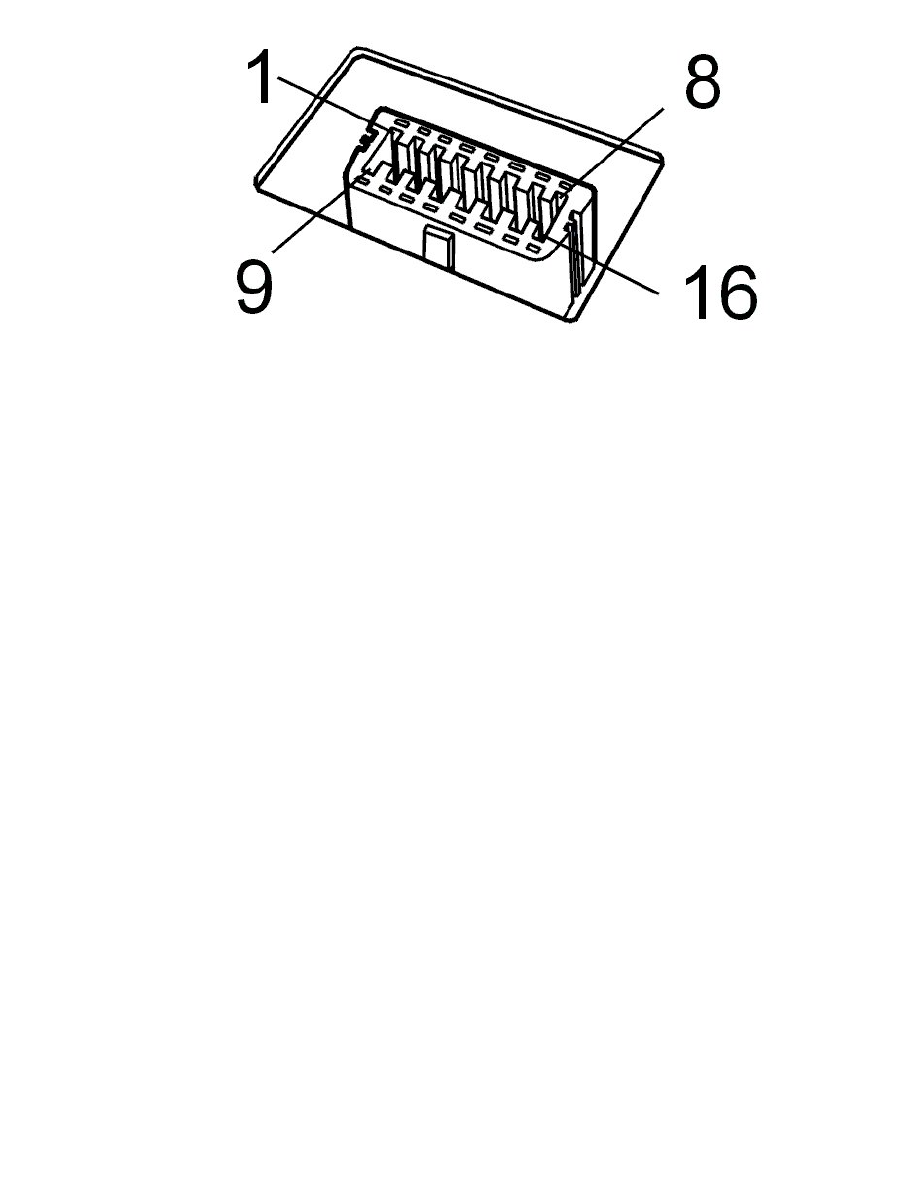
Diagnostic outlet
-
Check the voltage feed to diagnostic outlet #16. The voltage shall match battery voltage.
-
Check the cable for power ground and signal ground to diagnostic outlet #4 and #5.
Hint: When VCT2000 is connected to the diagnostic outlet (is supplied with voltage), the indicator diode shall be activated with a green light. Then the
indicator diode flashes quickly when communication takes place with a control module. In case of certain internal malfunctions on VCT2000 the
indicator diode is activated with a red light!
Communication cables
-
Check the communication cable (k-line) between diagnostic outlet #7 and central electronic module (CEM) #D6 and other connected control
modules for open circuit, short-circuit to ground and short-circuit to voltage.
Caution! In case of malfunction on this communication cable, communication cannot be established on either the low or high-speed