audi Workshop Repair Guides

Audi A1 Workshop Service and Repair Manuals

Removing and installing centre flap control motorV70 > < Removing and installing temperature sensor blowerV42
Removing and installing temperature flap control motorV68 and defroster flap control motorV107
Removing and installing temperature flap control motor -V68- and defroster flap control motor -V107-
  Note
t  The air intake unit contains various identical connectors. To avoid possible interchange, mark the connectors before unplugging.
t  Different control motors are fitted at the air conditioning unit and in the air intake unit. These motors have different electrical values and part number indices → Electronic parts catalogue. To avoid possible interchange, mark the control motors prior to removal.
t  Depending on the operating unit, Climatronic control unit -J255-, the temperature flap control motor -V68- on vehicles manufactured in 2010 may also be displayed as left temperature flap control motor -V158- → Vehicle diagnostic tester, „Guided fault-finding“ function.
   
Removing
–  Remove the dash panel → Rep. gr.70.
–  Remove the central tube → Rep. gr.70.
–  Unplug the connectors -1, 3, 5- and lay bare the wiring harness -4-.
–  Release the locking lugs -6-.
–  Swivel out the mount -2- for the control motors and disengage the guide pin.
  A87-10922
–  Carefully press the retainer tabs -arrows- outwards and take the control motor -A- out of the mount -B-.
  A87-0358
Installing
Install in reverse order, paying attention to the following:
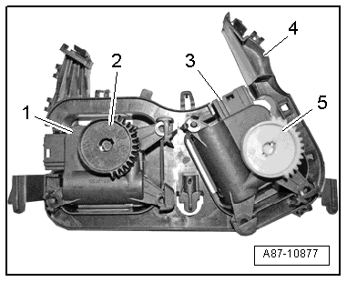
  Note
The mount for the control motors must be replaced if the retainer tabs in the mount have broken off.
–  Insert the new control motor in the mount -4-, paying attention to the assignment.
l  Temperature flap control motor -V68--Item 3-, colour of gear wheel -5- = black.
l  Defroster flap control motor -V107--Item 1-, colour of gear wheel -2- = white.
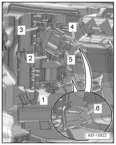
–  To check operation of the control motor, connect an adapter cable → Chapter or use a test lead from the adapter set -V.A.G 1594C- to connect contacts „5“ and „6“ of the control motor by way of a 5 A fuse to a 12 V battery.
  Note
t  Allow the control motor to turn as far as the stop. The direction of rotation can be reversed by interchanging positive and negative.
t  
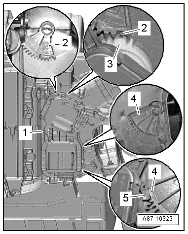
If one of the control motors is not in the installation position with respect to its gear wheel, it must be turned by applying 12 V to contacts „5“ and „6“.
  A87-10877
–  Move the lever for the defrost flap -2- and for the temperature flap -4- at the air distribution housing of the air conditioning unit to the position shown.
–  Insert the mount -1- at the housing, making sure that the gear wheel -3- at the defroster flap control motor engages in the gear wheel -2- at the defroster flap lever as shown.
  Note
Pay attention to correct mutual positioning of the gear wheels on assembly (short tooth and short gap).
–  The gear wheel -5- at the temperature flap control motor must engage in the gear wheel -4- at the temperature flap lever as shown.
–  Press the mount fully onto the housing.
–  Route the wiring harness such that it cannot come into contact with moving components (e.g. control motor lever).
On completion of repair work, perform the following operations on the operating unit in the „Guided fault-finding“ function → Vehicle diagnostic tester:
–  Interrogate the event recorder and delete any entries displayed.
–  Perform basic setting.
–  Perform final control diagnosis.
  A87-10923

Removing and installing centre flap control motorV70 > < Removing and installing temperature sensor blowerV42