
A1
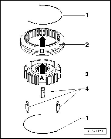
| Dismantling and assembling input shaft |
| Special tools and workshop equipment required |
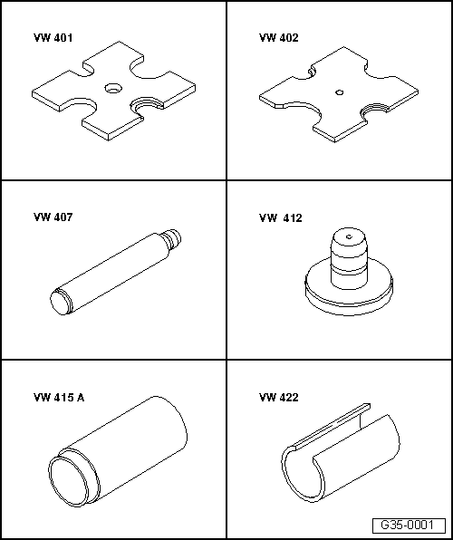
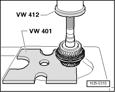
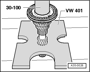
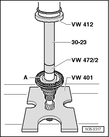
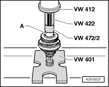
| t | Thrust plate -VW 401- |
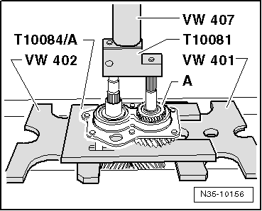
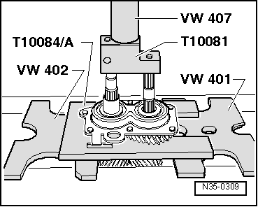
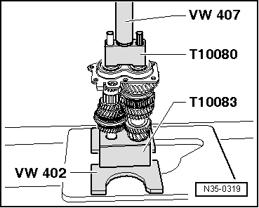
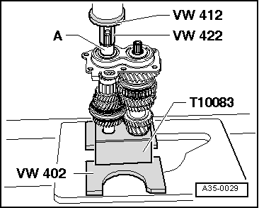
| t | Thrust plate -VW 402- |
| t | Press tool -VW 407- |
| t | Press tool -VW 412- |
| t | Tube -VW 415 A- |
| t | Tube -VW 422- |
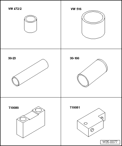
| t | Spacer sleeve -VW 472/2- |
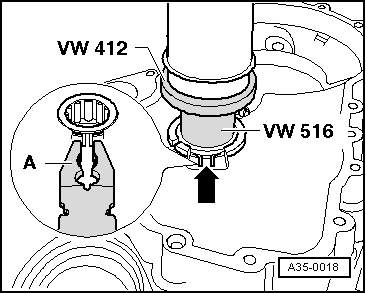
| t | Tube -VW 516- |
| t | Extension -30 - 23- |
| t | Drift sleeve -30 - 100- |
| t | Thrust piece -T10080- |
| t | Thrust piece -T10081- |
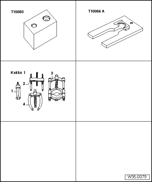
| t | Thrust block -T10083- |
| t | Thrust plate -T10084 A- |
| t | -1-Internal puller -Kukko 21/5- |
| t | -4-Counter-support -Kukko 22/2- |
|
|
|
|
|
|
|
|
|
|
|
|
|
|
|
|
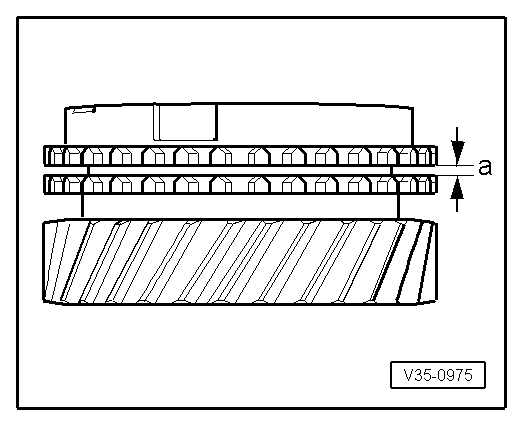
| Gap -a- | Installation depth | Wear limit |
| 3rd, 4th, 5th and 6th gear | 1.1 ... 1.7 mm | 0.5 mm |
|
|
|
|
|
|
|
|
| Measured value (mm) | Circlip thickness (mm) | Axial clearance (mm) |
| 0.05 … 0.14 | 2.0 | 0.05 … 0.15 |
| 0.15 … 0.24 | 2.1 | 0.05 … 0.15 |
| 0.25 … 0.34 | 2.2 | 0.05 … 0.15 |
| 0.35 … 0.44 | 2.3 | 0.05 … 0.15 |
| 0.45 … 0.51 | 2.4 | 0.05 … 0.10 |
|
|
 WARNING
|
|
|
|
|
|