
A3 Mk1
| Dismantling and assembling bevel box |

| Special tools and workshop equipment required |
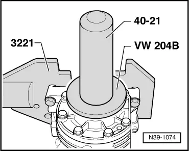
| t | Fitting tool -VW 204 B- |
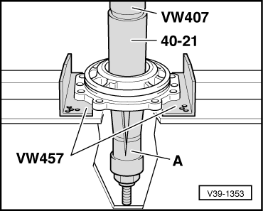
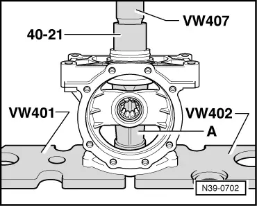
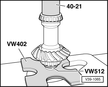
| t | Press tool -40-21- |
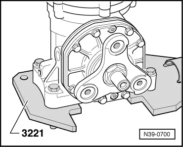
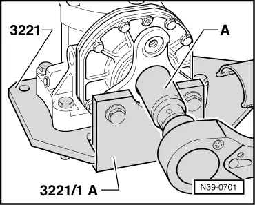
| t | Gearbox support -3221- |
| t | Support plate -3221/1 A - |
| t | Torque wrench -V.A.G 1601- |

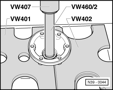
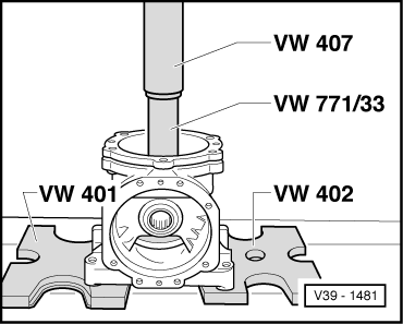
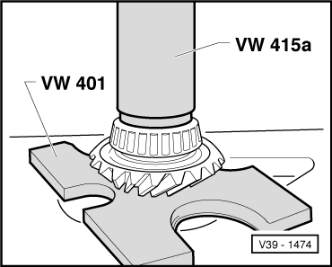
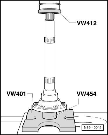
| t | Thrust plate -VW 401- |
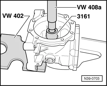
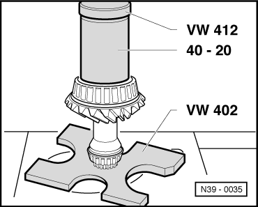
| t | Thrust plate -VW 402- |
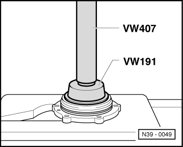
| t | Press tool -VW 407- |
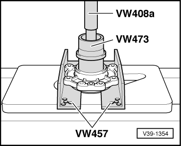
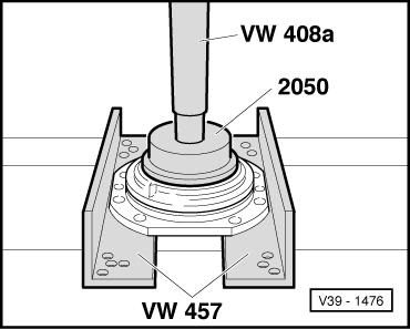
| t | Press tool -VW 408 A- |
| t | Tube -VW 415 A- |
| t | Torque wrench -V.A.G 1331- |

| t | Support rails -VW 457- |
| t | Press tool -VW 412- |
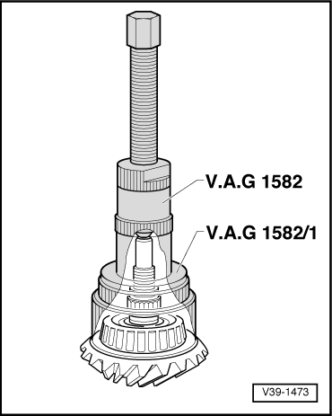
| t | Puller -V.A.G 1582- |
| t | Adapter -V.A.G 1582/1- |
| t | Press tool -VW 473- |
| t | Thrust plate -VW 447 H- |

| t | Fitting tool -VW 191- |
| t | Thrust piece -2050- |
| t | Tube -VW 460/2- |
| t | Press tool -VW 454- |
| t | -1-Internal puller -Kukko 21/3-, -Kukko 21/7-, -Kukko 21/8- |
| t | -3-Splitter -Kukko 17/2- |
| t | -4-Counter-support -Kukko 22/1-, -Kukko 22/2- |

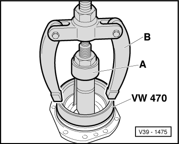
| t | Thrust pieces for pinion shaft bearing -VW 470- |
| t | Thrust pad -VW 512- |
| t | Tube -VW 771/33- |
| t | Drift sleeve -40-20- |
| t | Extension -3161- |
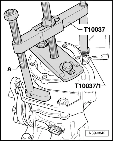
| t | Puller -T10037- |
|
|
|
|
 Note
Note
|
|
Note
|
|
|
|
|
|
|
|
|
|
|
|
|
|
|
|
|
|
Note
|
|
|
|
|
|
|
|
Note
|
|
Note
|
|
|
|
|
|
Note
|
|
|
|
|
|
Note
|
|
|
|
|
|
|
|