
A3 Mk1
| Dismantling and assembling output shaft for 1st - 4th gear |

| Special tools and workshop equipment required |
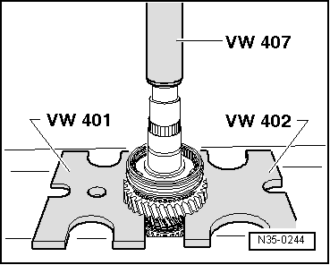
| t | Thrust plate -VW 401- |
| t | Thrust plate -VW 402- |
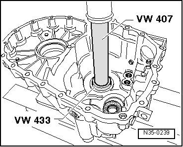
| t | Press tool -VW 407- |
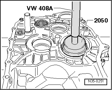
| t | Press tool -VW 408 A- |
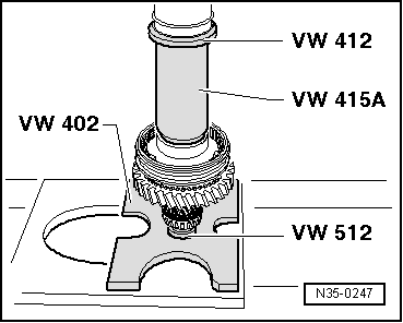
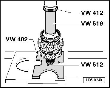
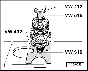
| t | Press tool -VW 412- |
| t | Tube -VW 415 A- |

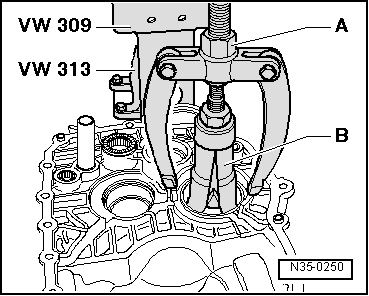
| t | Support plate -VW 309- |
| t | Support clamp -VW 313- |
| t | Gearbox support -VW 353- |
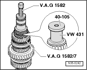
| t | Press tool -VW 431- |
| t | Press tool -VW 433- |
| t | Press tool -VW 454- |

| t | Thrust plate -VW 512- |
| t | Tube -VW 516- |
| t | Tube -VW 519- |
| t | Multi-purpose tool -VW 771- |
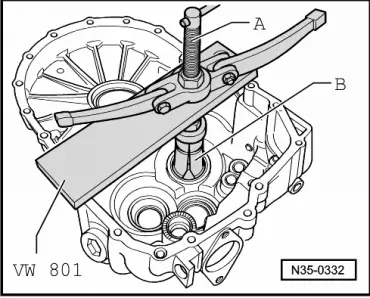
| t | Support plate -VW 801- |
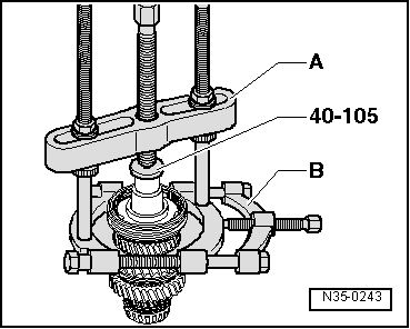
| t | Thrust plate -40-105- |

| t | Drift sleeve -40-20- |
| t | Drift sleeve -40-21- |
| t | Thrust piece -2050- |
| t | Extension -3161- |
| t | Tapered roller bearing puller -V.A.G 1582- |
| t | Adapter -V.A.G 1582/7- |
|
|
| Output shaft for 1st - 4th gear - exploded view of components |
 Note
Note| t | Refer to technical data → Chapter when installing new gears or a new output shaft. |
| t | Adjust output shaft after renewing output shaft or tapered roller bearings → Chapter. |

| 1 - | Clutch housing |
| 2 - | Oil deflector plate |
| 3 - | Dished washer |
| q | Pulling out → Fig. |
| q | Pressing in → Fig. |
| 4 - | Tapered roller bearing outer race |
| q | Pulling out → Fig. |
| q | Pressing in → Fig. |
| 5 - | Tapered roller bearing inner race |
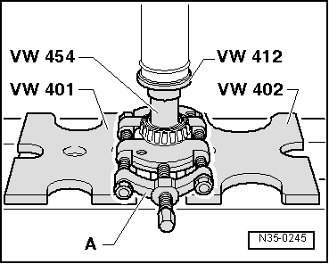
| q | Pressing off → Fig. |
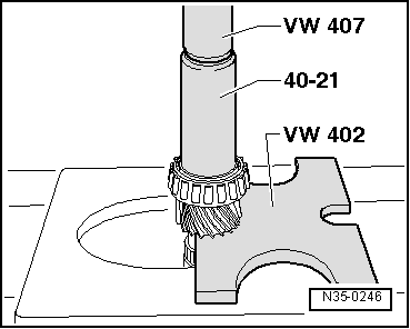
| q | Pressing on → Fig. |
| 6 - | Output shaft |
| q | For 1st to 4th gear |
| q | Adjusting → Chapter |
| 7 - | Needle bearing |
| q | For 2nd gear |
| 8 - | 2nd speed selector gear |
| 9 - | Synchro-ring |
| q | Inner ring for 2nd gear |
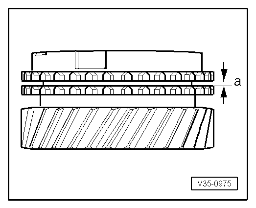
| q | Checking for wear → Fig. |
| q | Check lugs for scoring |
| q | Installation position → Fig. |
| 10 - | Outer ring for 2nd gear |
| q | Fit on synchro-ring → Item |
| q | Renew if scored or if there are visible traces of wear |
| q | Installation position → Fig. |
| 11 - | 2nd gear synchro-ring |
| q | Checking for wear → Fig. |
| q | Installation position → Fig. |
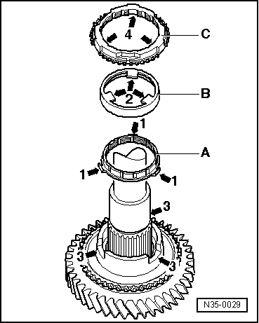
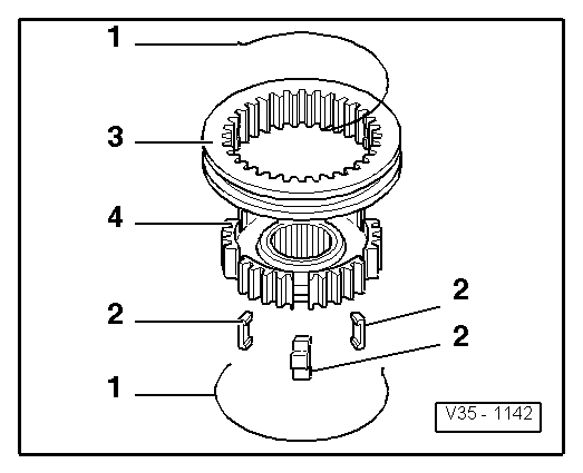
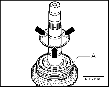
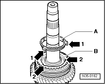
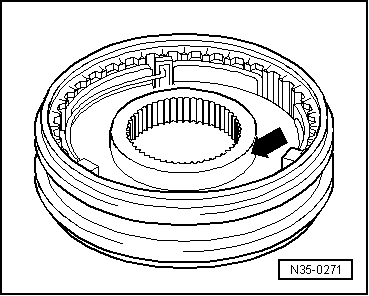
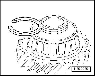
| 12 - | Locking collar with synchronising hub for 1st and 2nd gear |
| q | Press off together with bearing mounting → Fig. after removing circlip → Item |
| q | Dismantling → Fig. |
| q | Assembling locking collar/synchronising hub → Fig. and → Fig. |
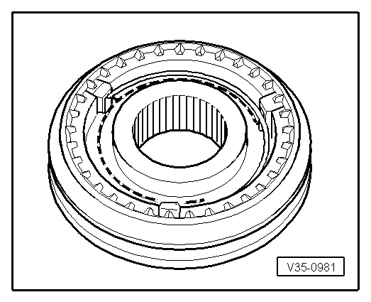
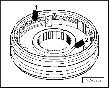
| q | Installation position → Fig. |
| q | Pressing on → Fig. |
| 13 - | Circlip |
| 14 - | 1st gear synchro-ring |
| q | Checking for wear → Fig. |
| q | Assemble so that the recesses engage on the locking pieces on the locking collar → Item |
| 15 - | Outer ring for 1st gear |
| q | Insert in synchro-ring → Item; installation position → Fig. |
| q | Renew if scored or if there are visible traces of wear |
| 16 - | Synchro-ring |
| q | Inner ring for 1st gear |
| q | Checking for wear → Fig. |
| q | Check lugs for scoring |
| q | Installation position → Fig. |
| 17 - | Needle bearing |
| q | For 1st gear |
| 18 - | 1st speed selector gear |
| q | Installation position → Fig. |
| 19 - | Thrust washers |
| q | For 1st and 4th gear |
| q | Insert lugs on thrust washer in hole on output shaft |
| 20 - | Washer |
| q | Holds thrust washers → Item in position on output shaft |
| 21 - | Needle bearing |
| q | For 4th gear |
| 22 - | 4th speed selector gear |
| 23 - | 4th gear synchro-ring |
| q | Checking for wear → Fig. |
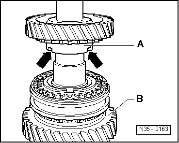
| 24 - | Locking collar with synchronising hub for 3rd and 4th gear |
| q | Pull off together with 4th speed selector gear after removing circlip → Item → Fig. |
| q | Dismantling → Fig. |
| q | Installation position: Locking collar/synchronising hub → Fig. |
| q | Assembling locking collar/synchronising hub → Fig. and → Fig. |
| q | Pressing on → Fig. |
| 25 - | Circlip |
| 26 - | 3rd gear synchro-ring |
| q | Checking for wear → Fig. |
| 27 - | Outer ring for 3rd gear |
| q | Insert in synchro-ring → Item; installation position → Fig. |
| q | Renew if scored or if there are visible traces of wear |
| 28 - | Synchro-ring |
| q | Inner ring for 3rd gear |
| q | Checking for wear → Fig. |
| q | Check lugs for scoring |
| q | Installation position → Fig. |
| 29 - | Needle bearing |
| q | For 3rd gear |
| 30 - | 3rd speed selector gear |
| q | Installation position → Fig. |
| 31 - | Tapered roller bearing inner race |
| q | Pulling off → Fig. |
| q | Pressing on → Fig. |
| 32 - | Circlip |
| q | When tapered roller bearing → Item or output shaft → Item are renewed: determine thickness of required circlip → Fig. |
| 33 - | Tapered roller bearing outer race |
| q | Pulling out → Fig. |
| q | Pressing in → Fig. |
| 34 - | Shim |
| q | Determining thickness → Chapter |
| 35 - | Gearbox housing |
|
|
|
|
|
|
|
|
|
|
|
|
|
|
|
|
|
|
|
|
|
|
|
|
|
|
|
|
|
|
|
|
|
|
|
|
|
|
|
|
|
|
|
|
|
|
| Circlips available (in mm) → Note | ||
| 1.79 | 1.89 | 1.98 |
| 1.83 | 1.92 | |
| 1.86 | 1.95 | |
|
|
|
|
|