audi Workshop Repair Guides

Audi Workshop Service and Repair Manuals

Adjusting engine mountings > < Attaching engine to engine stand
4-cyl. Diesel Direct Injection Engine (TDI), Mech. Components
Removing and installing engine
Installing

Special tools and workshop equipment required

  • ◆ Depth measurement (vehicles with automatic gearbox)

Procedure

  • ● Engine installed on engine bracket T10012.

Installation is carried out in the reverse order to removal, noting the following:

Notes:

  • ◆ When performing installation procedures always replace self-locking nuts and bolts.
  • ◆ Replace seals, gaskets, and bolts which have a specified tightening angle.
  • ◆ Hose connections and hoses for charge air system must be free of oil and grease before assembly.
  • ‒ Check whether the dowel sleeves for centralising engine/gearbox are in the cylinder block, install if necessary.
 
A10-0129
  • ‒ → Engage intermediate plate on sealing flange and slide onto dowel sleeves -arrows-.

Vehicles with manual gearbox

  • ‒ If necessary, check that clutch plate is properly centralised.
  • ‒ Check clutch release bearing for wear, renew if necessary.
  • ‒ Lightly lubricate clutch release bearing, release bearing guide sleeve and splines on input shaft with G 000 100.
  • ‒ Attach gearbox to engine.

Notes:

  • ◆ The tightening torques listed on this page apply only to lightly greased, oiled, phosphated, or black finished nuts and bolts.
  • ◆ Additional lubricant such as engine or gearbox oil may be used, but do not use graphite lubricant.
  • ◆ Do not use degreased parts.
  • ◆ Tightening torque tolerance ±15%.
 
A37-0214

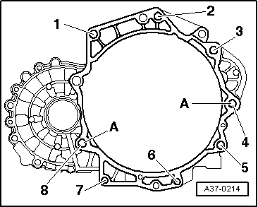
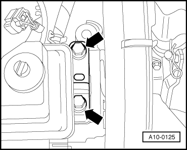
→ Engine/gearbox mountings (manual gearbox)

Item

Bolt

Nm

1, 2 1), 8

M12 x 55

80

3 1), 4

M12 x 150

80

5 ... 7

M10 x 50

45

    1)    Bolt with threaded pin M8

A: Centring sleeves

 
A34-0234
  • ‒ → Push in splash plate -2- in so that the lower lug engages into the cylinder block and secure at top with bolt -1-.
 
A32-0007

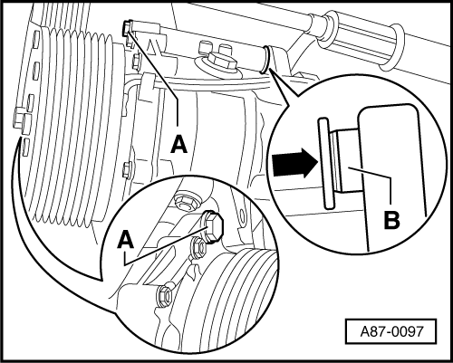
Vehicles with automatic gearbox:

  • ‒ To secure the torque converter on the drive plate only use the correct nuts as specified in the parts catalogue.

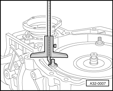
=> Parts List

→ If the torque converter is correctly installed, the depth between the contact surfaces at the bottom of the studs on the torque converter and the contact surface of the torque converter bell housing is about 22 mm.

If the torque converter has not been completely inserted, this distance will be approx. 10 mm.

Important
If the torque converter is not installed correctly, the torque converter drive plate or the ATF pump will be seriously damaged when the gearbox is joined to the engine.
  • ‒ Before installing engine, rotate torque converter and drive plate so that one hole and one stud are level with the aperture for the starter motor.
Important
On vehicles with automatic gearbox 01M, continually check that the torque converter behind the drive plate can be turned before and during tightening of bolts at engine/gearbox flange. If the converter cannot be turned, it must be assumed that it has not been installed correctly and the drive plate of the converter or the ATF pump will be damaged during final tightening of bolted connections.
  • ‒ Attach gearbox to engine.
  • ‒ Secure nuts of torque converter with special tool Matra V/175.

Notes:

  • ◆ The tightening torques listed on this page apply only to lightly greased, oiled, phosphated, or black finished nuts and bolts.
  • ◆ Additional lubricant such as engine or gearbox oil may be used, but do not use graphite lubricant.
  • ◆ Do not use degreased parts.
  • ◆ Tightening torque tolerance ±15%.
 
A37-0214

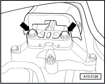
→ Securing engine to gearbox in vehicles with automatic gearbox

Item

Bolt

Nm

1, 2 1)

M12 x 65

80

3 1), 4 1)

M12 x 180

80

5 ... 7

M10 x 50

45

8

M12 x 80

80

    1)    Bolt with threaded pin M8

A: Centring sleeves

 
A10-0125

All models:

  • ‒ Guide engine/gearbox assembly into the body.
  • ‒ → Insert bolts -arrows- for engine support to engine console...
 
A10-0126
  • ‒ → ... and gearbox support to gearbox console handtight.
  • ‒ Only use new bolts to secure.

Note:

The bolts are tightened to final torque only after adjusting the engine mountings .

  • ‒ Remove engine bracket T10012 from engine.
  • ‒ Install drive shafts.

=> Running Gear; Repair group 40; Removing and installing drive shaft

Note:

Before further assembly carry out the installation of the drive shafts.

  • ‒ Install the connecting rod.

=> Running Gear; Repair group 40; Removing and installing stabiliser bar

 
A10-0928
  • ‒ → Bolt pendulum support to gearbox -arrows B-.
  • ‒ Only use new bolts to secure.

 
N34-0887
  • ‒ → Bolt pendulum support to subframe -arrows A-.
  • ‒ Only use new bolts to secure.
 
A87-0097

Vehicles with air conditioning:

  • ‒ → To facilitate the attachment of the air conditioner compressor drive back bush -B- for securing bolt -A- slightly.

Vehicles with manual gearbox

  • ‒ Install hydraulic clutch slave cylinder:

=> 5-speed Manual Gearbox 02J; Repair group 30; Servicing clutch release mechanism

  • ‒ Attach selector cables to gearbox and adjust:

=> 5-speed Manual Gearbox 02J; Repair group 34; Servicing shift mechanism; Removing and installing selector cables

The remaining installation steps are carried out in the reverse sequence.

  • ‒ Install ribbed belt=> Page 13-10.
  • ‒ Adjust engine mountings => Page 10-41.
  • ‒ Install vacuum hoses =>as of Page 21-19.
  • ‒ Electrical connections and routing:

=> Current Flow Diagrams, Electrical Fault-finding and Fitting Locations binder

Important
Do not use charging unit for boost starting! There is danger of damaging the vehicle control units.

Note:

If the battery is reconnected, please ensure that the vehicle equipment (radio, radio/navigation system, clock, electric window lifters) is activated as described in the operating instructions.

  • ‒ Top up coolant => Page 19-7.

Notes:

  • ◆ Drained coolant may only be used again if the original cylinder head and cylinder block are re installed.
  • ◆ Coolant must not be used again if it is dirty.
  • ‒ Check oil level before starting engine.

Tightening torques

Component

Nm

Bolts/nuts

M6

10

M8

20

M10

45

M12

65

Except for the following:

Drive plate to torque converter

M10 x1

85

Front exhaust pipe to exhaust turbocharger

25

Pendulum support to gearbox

40 + 90° 1)2)

Pendulum support to subframe

20 + 90°1)2)

Drive shaft heat shield to cylinder block

35

Air conditioner compressor to bracket for auxiliary mechanical units


45

Vane pump for power steering pump to bracket for auxiliary mechanical units


23

    1)    Stretch bolts, replace

    2)    90°corresponds to a quarter of a turn

Adjusting engine mountings > < Attaching engine to engine stand